Compound positioning spline milling clamp with center expansion sleeve and workpiece clamping and positioning method

A technology of compound positioning and sleeve expansion, applied in positioning devices, metal processing mechanical parts, clamping and other directions, can solve the problems of no grinding risk, error, unsatisfactory positioning and clamping method, etc., and achieve the effect of reducing connection errors.

Pending Publication Date: 2019-10-01
ANHUI XINGRUI GEAR TRANSMISSION
View PDF0 Cites 0 Cited by
  • Summary
  • Abstract
  • Description
  • Claims
  • Application Information

AI Technical Summary

Problems solved by technology

There may be indentations on the bearing gear, which may cause the risk of grinding out
[0003] There are other solutions such as "two tops + expansion sleeve clamping and positioning". After the two tops withstand the spline shaft, the expansion sleeve clamps the spline shaft to prevent rotation. At this time, the expansion sleeve and one of the tops There is a certain error in the combination
[0004] At present, the positioning and clamping methods of the existing spline milling process are not ideal, and it is necessary to provide a new positioning and clamping method

Method used


Image

  • Compound positioning spline milling clamp with center expansion sleeve and workpiece clamping and positioning method
  • Compound positioning spline milling clamp with center expansion sleeve and workpiece clamping and positioning method

Examples


Embodiment Construction

[0021] It should be noted that, in the case of no conflict, the embodiments in the present application and the features in the embodiments can be combined with each other. The present invention will be described in detail below with reference to the accompanying drawings and examples.

[0022] figure 1 with figure 2 Some embodiments according to the invention are shown.

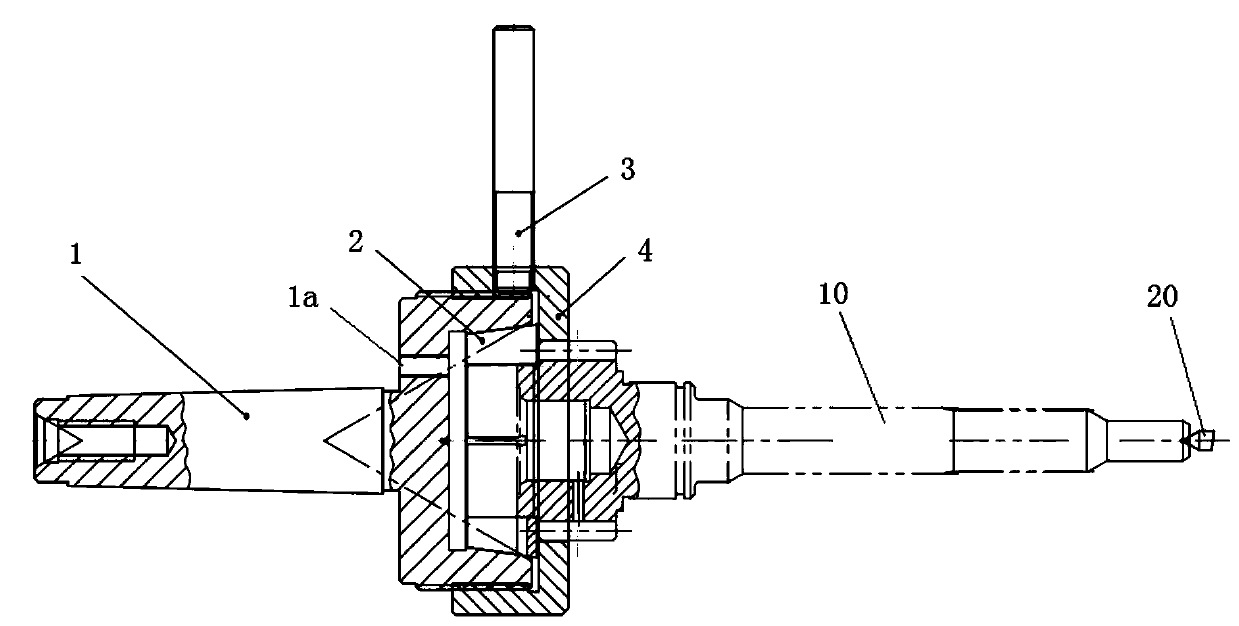
[0023] Such as figure 1 As shown, the spline milling fixture includes a main clamping part and an auxiliary clamping part.

[0024] The main clamping part is composed of the top shaft 1, the expansion sleeve 2 and the top of the machine tool. The axial force of the machine tool top is transmitted to the axial force required for the positioning of the expansion sleeve through the end surface of the workpiece and the expansion sleeve 2.

[0025] The auxiliary clamping part is composed of a handle 3 and a screw platen 4 .

[0026] When the spline milling fixture is in use, the top shaft 1 is connected with...


PUM


Abstract

The invention discloses a compound positioning spline milling clamp with a center expansion sleeve and a workpiece clamping and positioning method. The workpiece clamping and positioning method comprises the following steps of 1, fixing a center shaft of the compound positioning spline milling clamp with the center expansion sleeve on a machine tool; 2, putting the outer circle of a workpiece intoan inner hole of the expansion sleeve of the compound positioning spline milling clamp with the center expansion sleeve so that the end face of the workpiece can be close to the end face of the expansion sleeve; 3, ejecting a center hole of the workpiece by a center of a spline milling machine to push the workpiece to move horizontally and axially, and forcing the expansion sleeve to shrink inward to position and clamp the workpiece; and 4, rotating the spiral pressing plate, wherein the spiral plate moves axially in the horizontal direction and presses the end face of the expansion sleeve tostop retraction. According to the compound positioning spline milling clamp with the center expansion sleeve and the workpiece clamping and positioning method, the ideal positioning and clamping method is provided for spline milling process, and the center force of the spline milling machine is used to clamp the workpiece, so that the labor intensity is reduced, and the outer circle of the workpiece clamped by the expansion sleeve has no indentation and other appearance defects.

Description

technical field [0001] The invention relates to a spline milling fixture for compound positioning of a top expansion sleeve and a workpiece positioning and clamping method for the spline milling process of a spline shaft of a transmission. Background technique [0002] In the machining of spline shafts of transmissions of vehicles and engineering machinery, when milling splines, two centers are usually used for positioning and manual clamping with conventional chicken heart chucks. Manual clamping requires a large force, which brings labor intensity. Big question. There may be indentations at the bearing gear, which may cause the risk of not being worn out. [0003] There are other solutions such as "two tops + expansion sleeve clamping and positioning". After the two tops withstand the spline shaft, the expansion sleeve clamps the spline shaft to prevent rotation. At this time, the expansion sleeve and one of the tops There is a certain error in the combination. [0004]...

Claims


Application Information

Patent Timeline
Patent Type & Authority Applications(China)
IPC IPC(8): B23Q3/12
CPCB23Q3/12
Inventor 谢建安苏敏
Owner ANHUI XINGRUI GEAR TRANSMISSION
Why Eureka
Try Eureka