Taper clutch brake device

A brake device and taper technology, which is applied in the field of clutches, can solve the problems of increasing the safety risk of processing equipment, the shaft cannot be stopped quickly, and the single function, so as to improve transmission efficiency and braking efficiency, improve processing efficiency, and improve safety performance Effect

Pending Publication Date: 2019-10-01
文武
View PDF0 Cites 0 Cited by
  • Summary
  • Abstract
  • Description
  • Claims
  • Application Information

AI Technical Summary

Problems solved by technology

[0003] At present, most of the existing industrial clutches are electromagnetic or pneumatic friction type, but there are problems in these two types of clutches. Electromagnetic clutches use current to pass through the magnetic induction coil to generate a magnetic field, and the clutch plate is attracted, so that the driven wheel and the driving wheel are connected. The wheel combination will generate a lot of heat during the suction process. Poor heat dissipation or high ambient temperature will cause the electromagnetic coil to overheat and burn out. The pneumatic friction clutch mainly adopts plane friction clutch, and the clutch plate generally adopts It is made of asbestos or other compound materials. These materials will generate a lot of heat during the clutching process, causing them to decompose and oxidize, affecting the service life of the stand. At the same time, a large amount of harmful gases will be generated, which is poor in environmental protection. Another disadvantage is It is easy to slip, has poor stability, and poor use effect. In addition, most of the existing industrial clutches can only play the role of clutch, and the function is relatively single. Static, which greatly reduces the processing efficiency of the processing equipment. At the same time, it also increases the safety risk of the processing equipment. Currently, clutches and brakes are two different accessories. Most manufacturers design them separately. If they are used together, it is inconvenient to use. The stability is also poor, resulting in a larger volume of the entire device and a larger footprint, which reduces the use of the peripheral space and requires a higher site

Method used


Image

  • Taper clutch brake device
  • Taper clutch brake device
  • Taper clutch brake device

Examples


Embodiment Construction

[0034] The following are specific embodiments of the present invention and in conjunction with the accompanying drawings, the technical solutions of the present invention are further described, but the present invention is not limited to these embodiments.

[0035] This clutch brake device is mainly aimed at the improvement of clutches or reducers in various processing and manufacturing equipment manufactured in the existing industry, but for its integrated function of clutch and brake, this structure is not limited to be used in processing Or manufacturing equipment, but also applicable to other fields such as automobiles.

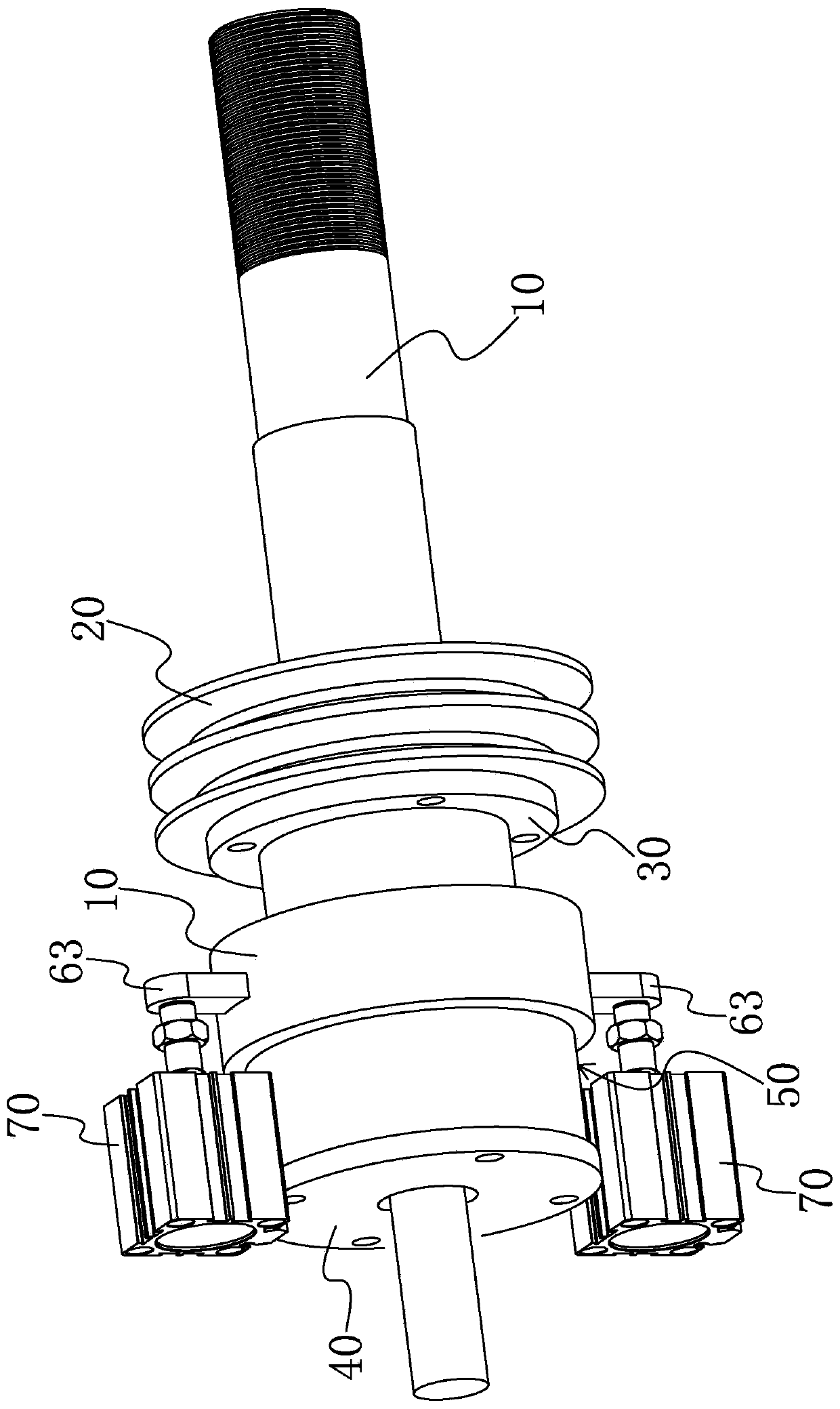
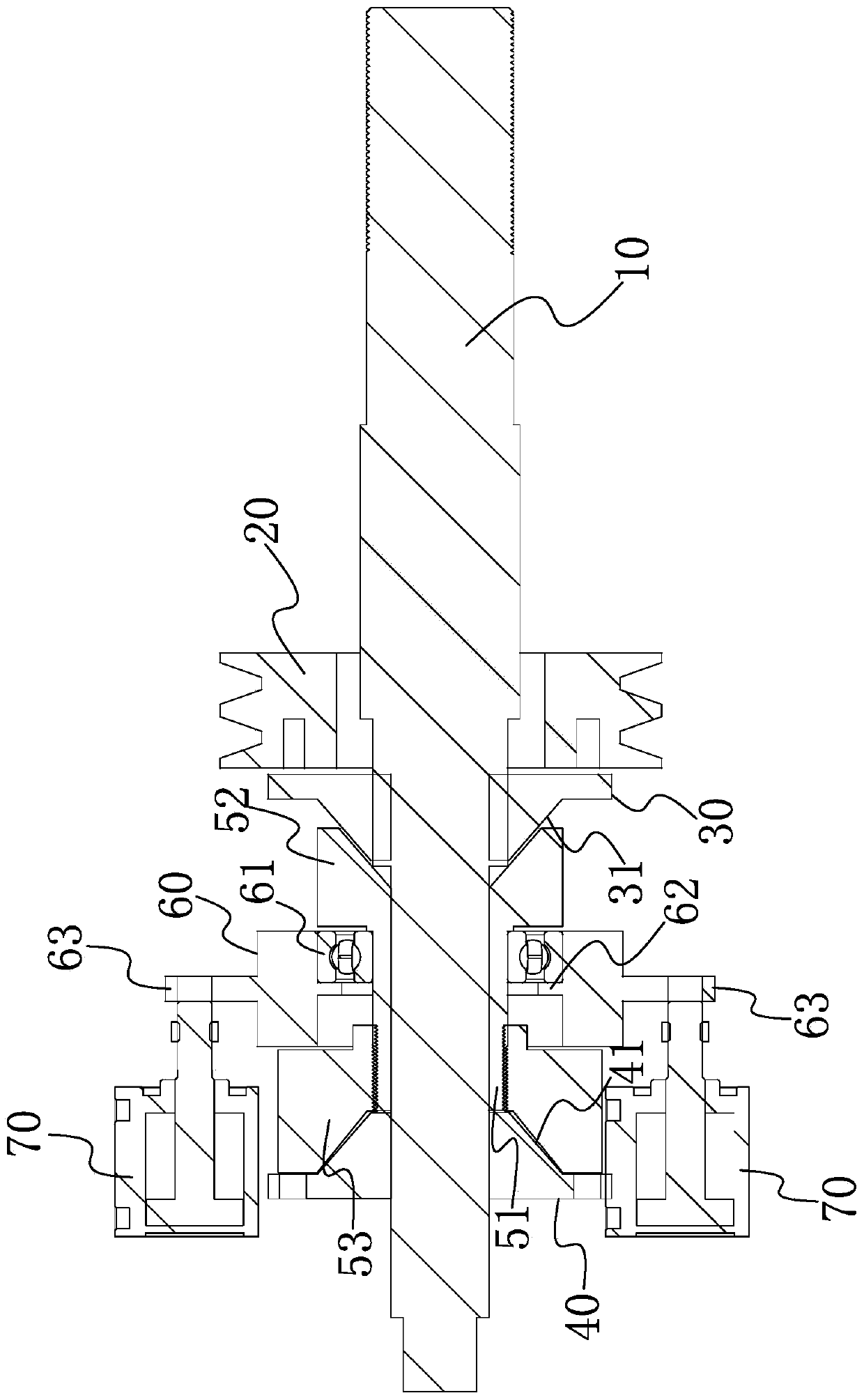
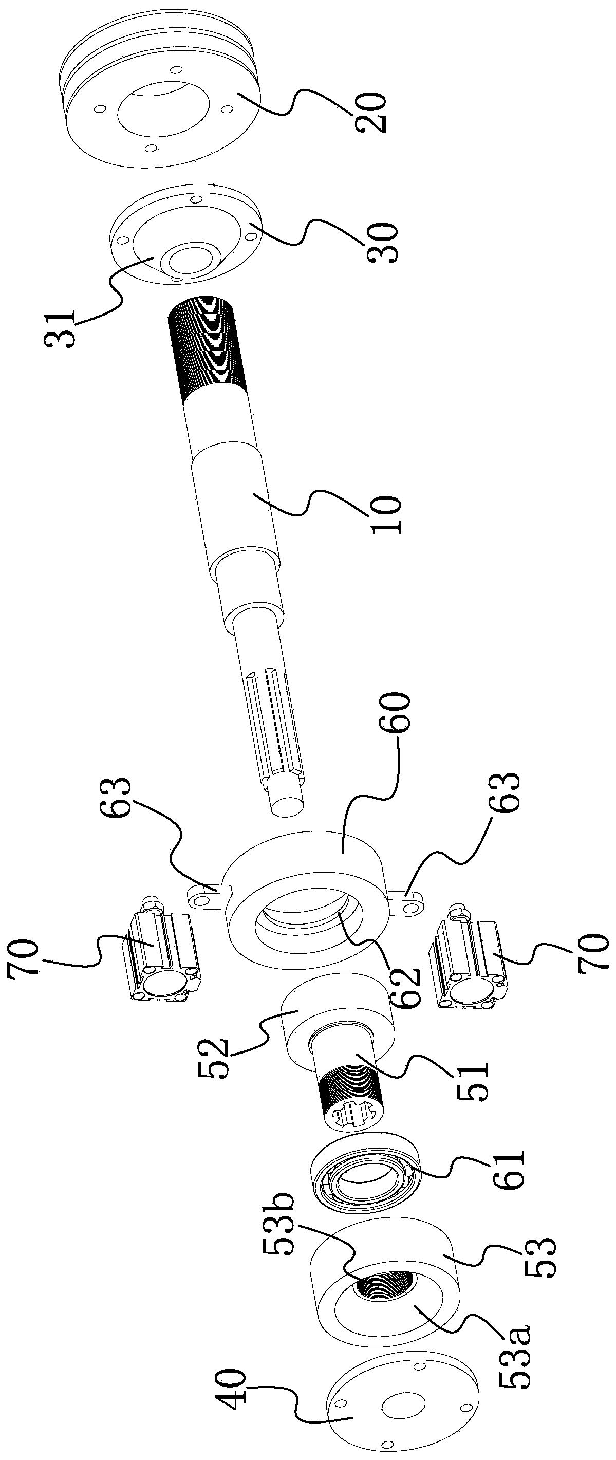
[0036] Such as Figure 1-Figure 4 As shown, a taper clutch braking device of the present invention mainly includes a transmission shaft 10 , a driving wheel 20 , a transmission seat 30 , a brake seat 40 and a transmission member 50 .

[0037] The transmission shaft 10 is axially extended, and the driving wheel 20 is installed on the transmission shaft 10...


PUM


Abstract

The invention provides a taper clutch brake device, and belongs to the technical field of clutches. The taper clutch brake device solves the technical problems that an existing clutch is short in service life, and poor in the stability are solved. The taper clutch brake device comprises a transmission shaft, a driving wheel, a transmission seat, a brake seat and a transmission part, wherein the transmission shaft extends in the axial direction; the driving wheel is arranged on the transmission shaft and is axially fixed with the transmission shaft; the transmission seat is fixedly connected with the driving wheel and can synchronously rotate along with the driving wheel, the transmission shaft penetrates through the transmission seat; the brake seat is fixedly arranged and separated from the transmission seat, the transmission shaft penetrates through the brake seat; and the transmission part is fixedly connected to the transmission shaft in the circumferential direction, the transmission part is located between the transmission seat and the brake seat and is separated from the transmission seat and the brake seat, and the transmission part can axially move relative to the transmission shaft. According to the conical surface-contacted matching structure, so that when the transmission part is in contact with the transmission seat or the brake seat, the force in the radial direction and the axial direction is generated at the same time, the transmission and braking effects are good, the clutch and braking are combined in the whole structure, the structure is simple, and the structure compactness is good.

Description

technical field [0001] The invention belongs to the technical field of clutches, and relates to a clutch device, in particular to a taper clutch and brake device with a braking function. Background technique [0002] Clutches are widely used. They are not only used in the flywheel housing between the engine and gearbox of automobiles to temporarily separate and engage the engine and gearbox. They are also widely used in processing equipment such as machine tools or lathes. That is to say, the so-called industrial clutch, which can realize the rotation or stop of the shaft when the motor continues to drive the pulley to rotate, thereby avoiding repeated electronic start and stop, prolonging the service life of the motor and reducing energy consumption . [0003] At present, most of the existing industrial clutches are electromagnetic or pneumatic friction type, but there are problems in these two types of clutches. Electromagnetic clutches use current to pass through the mag...

Claims


Application Information

Patent Timeline
Patent Type & Authority Applications(China)
IPC IPC(8): F16D67/02
CPCF16D67/02
Inventor 文武
Owner 文武
Why Eureka
Try Eureka