On-orbit calibration method

A calibration method and attitude adjustment technology, applied in the aerospace field, can solve problems such as reducing navigation accuracy

Active Publication Date: 2019-10-01
CENT SOUTH UNIV
View PDF9 Cites 5 Cited by
  • Summary
  • Abstract
  • Description
  • Claims
  • Application Information

AI Technical Summary

Problems solved by technology

[0004] The existing inertial group calibration method on the aircraft uses the fusion information of satellite navigation and star sensors to realize the calibration of the gyroscope and accelerometer error items, but only involves the gyroscope error item, the redundant gyroscope error item, and the conventional inertial set error item As well as the installation error of the star sensor, the redundant inertial group on the aircraft cannot calibrate all the observable error items including the installation error of the star sensor at one time. In the process of successive calibration, the drift errors of various devices will affect each other, reducing the navigation precision

Method used


Image

  • On-orbit calibration method
  • On-orbit calibration method
  • On-orbit calibration method

Examples


Embodiment 1

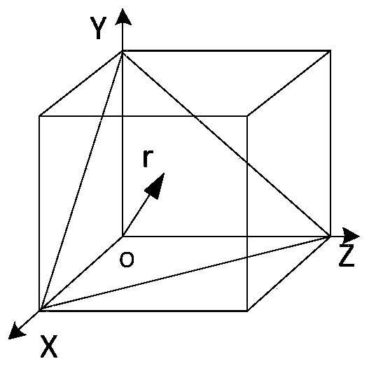
[0065] An on-orbit calibration method based on satellite navigation and star sensor information fusion with redundant inertial groups for aircraft, using optical fiber four-axis redundant inertial groups, specifically: it consists of four gyroscopes and four accelerometers, three of which are Orthogonal installation with three accelerometers is the orthogonal axis (X-axis, Y-axis and Z-axis), and another gyroscope and accelerometer are installed obliquely, which is the redundant axis (r-axis), such as figure 1 shown. The included angle between the redundant axis and the other three axes is the same, 54.74°. The star sensor is installed in strapdown with the redundant inertial group, and the optical axis of the star sensor is in the same direction as the Y-axis of the redundant inertial group. Define OXYZ as the system of the inertial group, denoted as b system. The four-axis redundant inertial group must be calibrated before use to compensate for sensor errors. In general, ...

Embodiment 2

[0129] The only difference between this embodiment and Embodiment 1 is that when adjusting the posture, first rotate 45° around the Z axis, then rotate 45° around the X axis, and finally rotate 45° around the Y axis; when resetting, first rotate -45° around the Y axis °, then rotate -45° around the X axis, and finally rotate -45° around the Z axis.

[0130] All the observable error items of the four-axis redundancy inertial group in this embodiment can be estimated at one time; the size of the calibration value is greater than more than 90% of the constant value error item, and the calibration result is correct. Calibration method of observation error term.

Embodiment 3

[0132] The only difference between this embodiment and Embodiment 1 is that when adjusting the posture, first rotate 15° around the Z axis, then rotate 15° around the X axis, and finally rotate 15° around the Y axis; when resetting, first rotate -15° around the Y axis °, then rotate -15° around the X axis, and finally -15° around the Z axis.

[0133] All the observable error items of the four-axis redundancy inertial group in this embodiment can be estimated at one time; the size of the calibration value is greater than more than 90% of the constant value error item, and the calibration result is correct. Calibration method of observation error term.


PUM


Abstract

The invention provides an on-orbit calibration method. The on-orbit calibration method comprises a preparation step, a posture adjustment reset step, an observation step and a static drift measurementstep; the preparation step specifically comprises: connecting a redundant inertial group, a GPS, a star sensor and an acquisition computer; after an aircraft enters a predetermined orbit, beginning to acquire redundant inertial group data, GPS data and star sensor data; the posture adjustment reset step specifically comprises: the star sensor rotates at a certain angle around an axis; the observation step specifically comprises: performing star observation and GPS speed observation; and, the acquisition computer performs iterative calculation solving by utilizing a standard Kalman filter, sothat a calibration result is obtained; and the calibration result comprises the gyro zero bias, a scale factor, the installation error, the meter adding zero bias and the star inertial installation error; by adoption of the technical scheme in the invention, all observable error terms of the redundant inertial group can be estimated for one time; the calibration value is greater than 90% of the constant error item; and the calibration result is correct.

Description

technical field [0001] The invention relates to the field of aerospace technology, in particular to an on-orbit calibration method of redundant inertial groups for aircraft based on satellite navigation and star sensor information fusion. Background technique [0002] In order to meet the long-term reliability, safety and high-accuracy requirements of the inertial group on the aircraft, the guidance method using redundant inertial group will become the development trend of the guidance system. [0003] The inertial navigation system (INS) can provide continuous and comprehensive navigation information for the carrier through gyroscopes and accelerometers, and has been widely used in military and civilian fields. However, navigation errors can accumulate in this system over time. Therefore, INS can be integrated with other navigation means to overcome the divergence of navigation errors over time. Celestial navigation is another completely autonomous navigation method, whic...

Claims


Application Information

Patent Timeline
Patent Type & Authority Applications(China)
IPC IPC(8): G01C25/00
CPCG01C25/00G01C25/005
Inventor 芦佳振叶莉莉韩松来董晶桂明臻罗世彬
Owner CENT SOUTH UNIV
Why Eureka
Try Eureka