
Strong impact test adjusting device and method suitable for carrier-based electronic equipment

A technology for impact testing and electronic equipment, which is applied in the direction of impact testing, measuring devices, and testing of machine/structural components, etc. It can solve problems such as under-testing, inconsistency between impact-resistant design input indicators and impact assessment test values, and equipment over-testing. , to achieve the effect of improving equipment and facilitating shipboard electronic equipment

Active Publication Date: 2019-10-01
CHINA ELECTRONICS TECH GRP CORP NO 14 RES INST
View PDF4 Cites 1 Cited by
  • Summary
  • Abstract
  • Description
  • Claims
  • Application Information

AI Technical Summary

Problems solved by technology

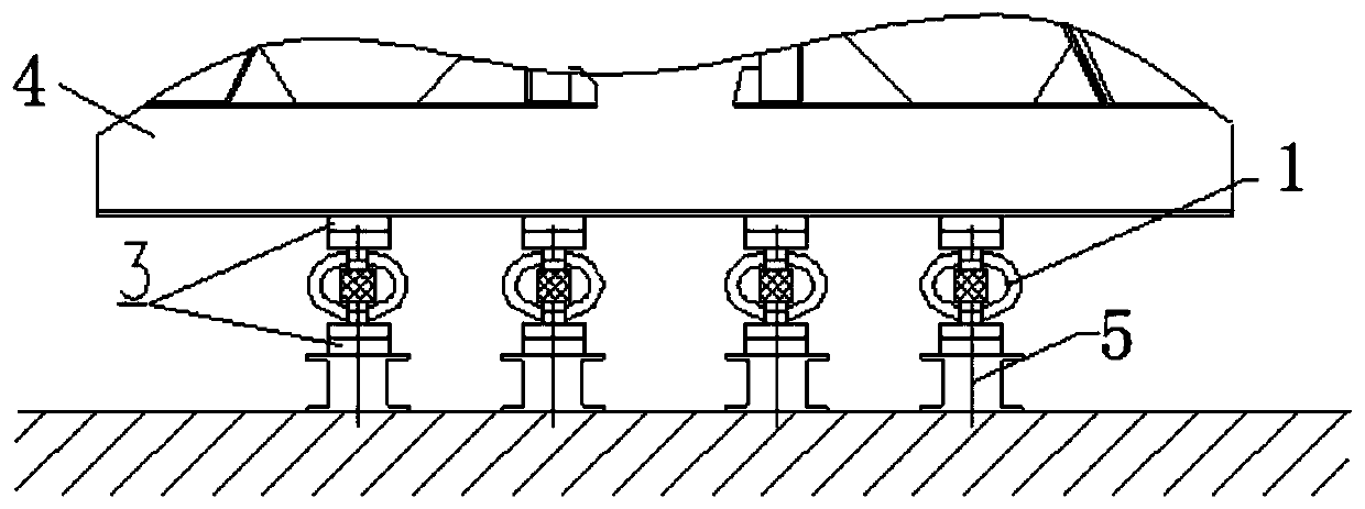
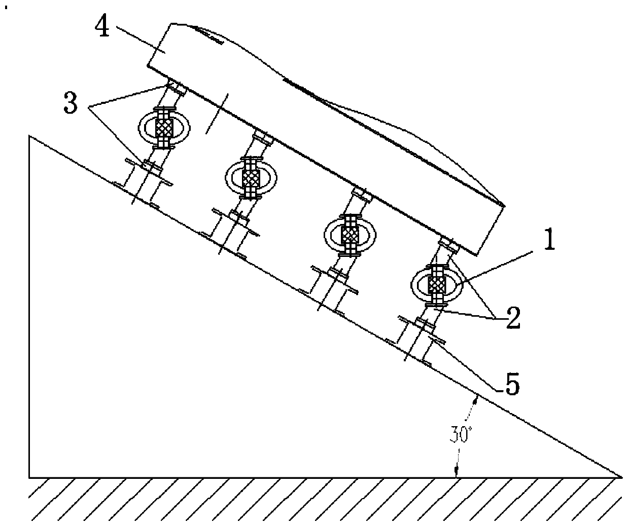
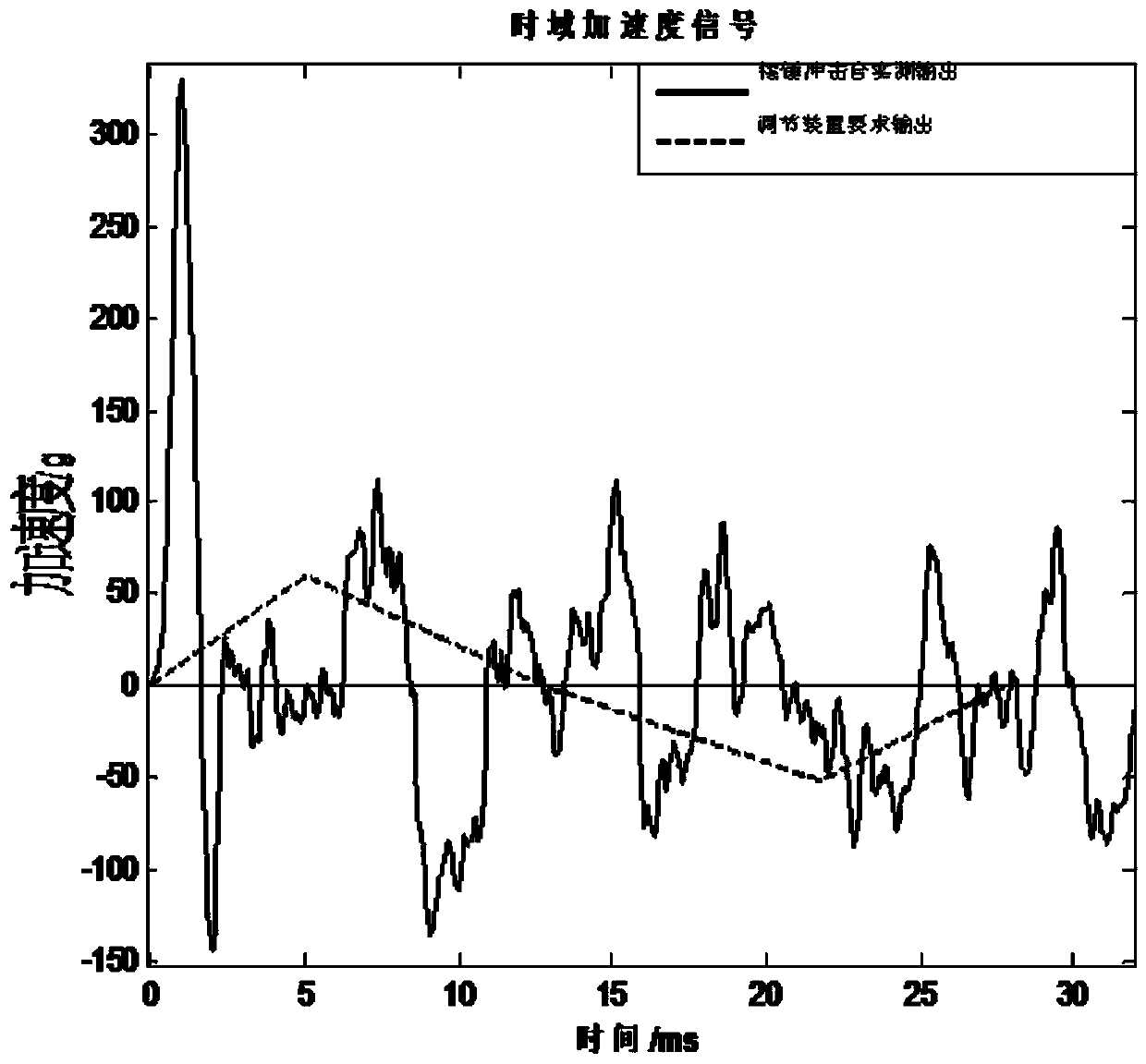
[0007] In view of the above problems, the present invention provides a strong impact test adjustment device and method suitable for shipboard electronic equipment, through which the output of the pendulum impact test bench can be adjusted to the impact output of a given frequency and amplitude, which solves the problem of The problem of over-testing or under-testing of equipment caused by the inconsistency between the input index of equipment shock resistance design and the value of shock assessment test, as well as the problem of decomposition of shock resistance index and verification of shock resistance ability of modules in large and complex shipboard electronic systems, and provides a New check test method

Method used


Image

  • Strong impact test adjusting device and method suitable for carrier-based electronic equipment
  • Strong impact test adjusting device and method suitable for carrier-based electronic equipment
  • Strong impact test adjusting device and method suitable for carrier-based electronic equipment

Examples


Embodiment Construction

[0074] The present invention will be further elaborated below.

[0075] Such as Figures 1 to 7-2 As shown, the present invention provides a strong impact test adjustment device suitable for shipboard electronic equipment, including an adjustment module 1 , a transition bracket 2 , and a connecting plate 3 . The adjustment module 1 includes a wire rope shock absorber 10 , a rubber plate 11 and a steel plate 12 . A steel plate 12 is installed in the length direction of the wire rope damper 10, and rubber plates 11 are arranged above and below the steel plate 12. The steel plate 12 is connected with the wire rope damper through the rubber plate 11. The steel plate 12 and the rubber plate 11 fill the wire rope damper 10 vertically. direction. The equipment under test is connected to the transition bracket 2 through a connecting plate 3 , and the test bench is connected to another transition bracket 2 through another connecting plate 3 ; the adjustment module 1 is connected betw...


PUM


Abstract

The invention discloses a strong impact test adjusting device and method suitable for carrier-based electronic equipment. The device comprises an adjusting module and a connecting plate; the adjustingmodule comprises a steel wire rope vibration absorber, rubber plates and steel plates; steel plates are installed in the length direction of the steel wire rope vibration absorber, rubber plates arearranged on the upper portion and the lower portion of the steel plates, the steel plates are connected with the steel wire rope vibration absorber through the rubber plates, and the steel plates andthe rubber plates are filled in the vertical direction of the steel wire rope vibration absorber. In the horizontal test, the tested equipment is connected with the adjusting module through a first connecting plate, a test bed is connected with the adjusting module through a second connecting plate, and the adjusting module is arranged between the first connecting plate and the second connecting plate. The problem of over-test or under-test in the strong impact test of the carrier-based electronic equipment is solved, a new idea and a new technical approach are provided for the decomposition and check test of the strong impact resistance index of the subsystem equipment in a system, and the design and research of the strong impact resistance structure of the carrier-based electronic equipment, particularly the complex large-scale carrier-based electronic equipment, are facilitated.

Description

technical field [0001] The invention relates to an impact adjustment device, which is particularly suitable for shipboard electronic equipment to be installed on the adjustment device to perform a strong impact check test. Background technique [0002] The anti-shock ability of ships and shipboard electronic equipment is an important factor that determines the vitality of ships in wartime. It directly affects the combat effectiveness of ships and is an overall capability that affects the comprehensive performance of the entire ship (boat). For this reason, Western naval powers have been exploring for a long time to formulate anti-shock standards for ship equipment and technical systems for anti-shock design and assessment of ship equipment, and to standardize the entire process of ship equipment design, manufacturing, and acceptance. The research work on anti-shock of ships in my country started relatively late, and the anti-shock design and assessment requirements of existi...

Claims


Application Information

Patent Timeline
IPC IPC(8): G01M7/08
CPCG01M7/08
Inventor 杨斌周世新徐俊东罗震
Owner CHINA ELECTRONICS TECH GRP CORP NO 14 RES INST
Learn More