
Nuclear reactor reactivity control mechanism

A technology for reactivity control and nuclear reactors, applied in nuclear reaction control, reactors, nuclear engineering, etc., can solve the problems of occupying the core grid, increasing the radial size of the core, and controlling rod components that cannot rely solely on gravity conditions, etc. To achieve the effect of compact structure, simple system and reliable function

Inactive Publication Date: 2019-10-01
CHINA INSTITUTE OF ATOMIC ENERGY
View PDF9 Cites 11 Cited by
  • Summary
  • Abstract
  • Description
  • Claims
  • Application Information

AI Technical Summary

Problems solved by technology

However, for the control mechanism of the above-mentioned structural forms, the first operation mode is linear reciprocating motion up and down, and the design, manufacture and application of the control mechanism must consider the effect of gravity; second, the above-mentioned structural forms are all arranged inside the core, occupying The core grid, the radial dimension of the core becomes larger, and in some special operating environments, the reactor core is required to be small and light, and the rapid drop of the control rod assembly cannot rely solely on gravity conditions. For this type of nuclear power reactor , none of the existing reactive control mechanisms can meet its functional requirements

Method used


Image

  • Nuclear reactor reactivity control mechanism
  • Nuclear reactor reactivity control mechanism
  • Nuclear reactor reactivity control mechanism

Examples


Embodiment Construction

[0027] The present invention will be further described below in conjunction with the accompanying drawings and embodiments.

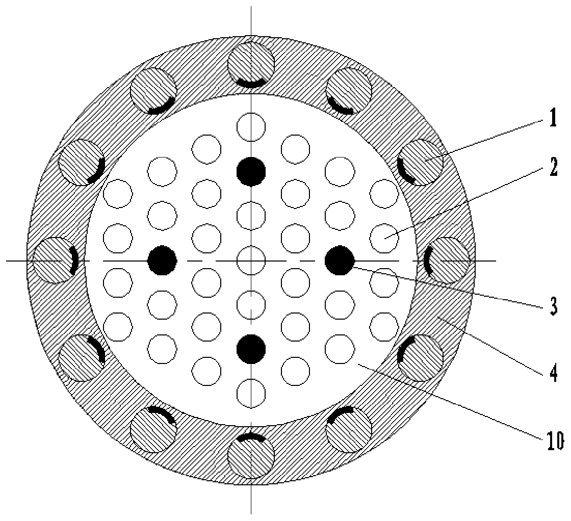
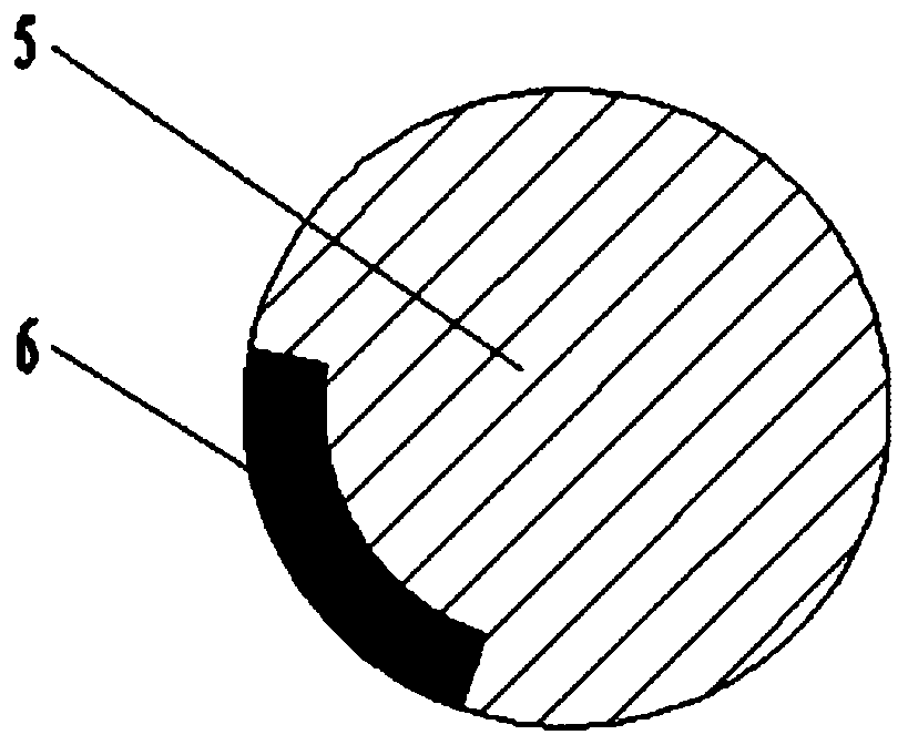
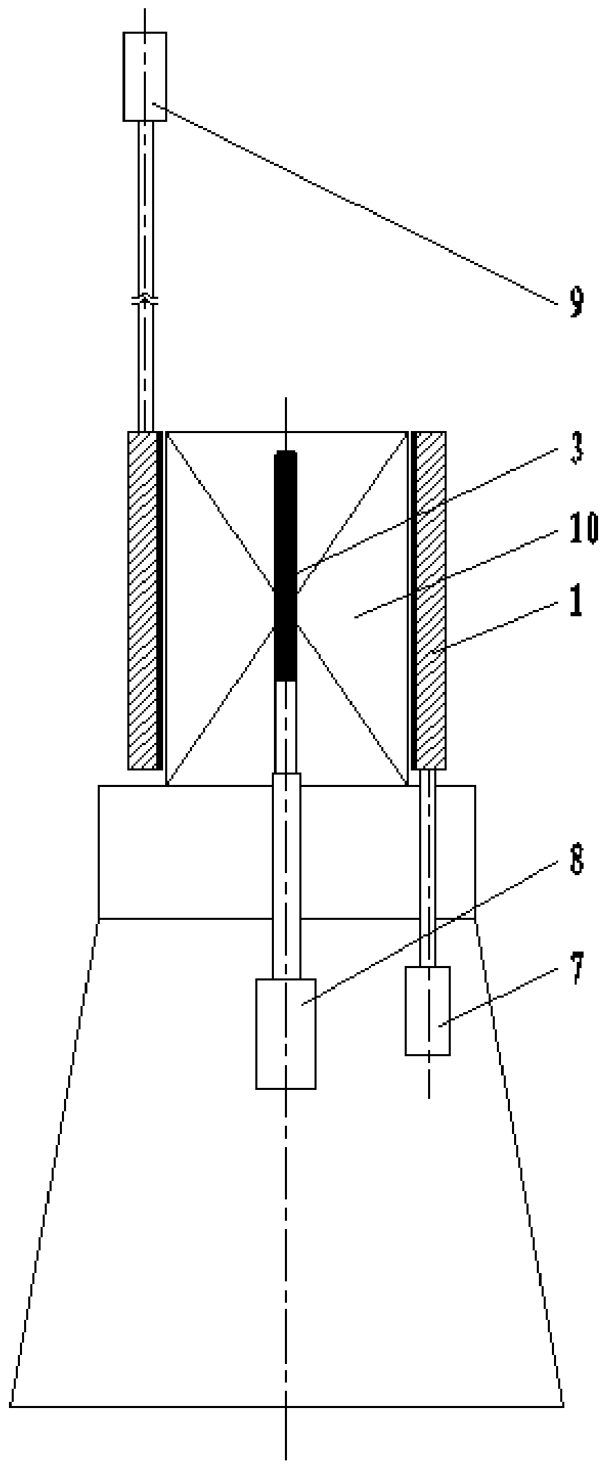
[0028] Such as figure 1 , image 3 As shown, a nuclear reactor reactivity control mechanism provided by the present invention includes a control rod assembly 1, a safety rod assembly 3, a core reflector 4, a first control rod drive mechanism 7, a safety rod drive mechanism 8 and a second control rod Drive mechanism 9 etc. parts.

[0029] figure 1 Shown is the layout of the nuclear reactor core. The core of this type of nuclear reactor is required to be extremely compact. The core reflector 4 is a ring structure with openings at both ends (the core reflector 4 is spliced ​​by multiple parts). The core reflector 4 The interior can accommodate the core 10 of the nuclear reactor, and the core 10 is a core grid equipped with several cylindrical fuel assemblies 2 . According to the result of the physical design of the core, a certain number of safety rod ...


PUM


Abstract

The invention belongs to the technical field of nuclear reactor reactivity control and particularly relates to a nuclear reactor reactivity control mechanism which comprises a safety rod assembly arranged in a core of a nuclear reactor and capable of going in or out of the core through reciprocating motion, wherein a core lattice for mounting a fuel assembly is arranged in the core. The nuclear reactor reactivity control mechanism further comprises a plurality of cylindrical and rotatable control rod assemblies arranged in the annular reflecting layer on the outer side of the reactor core, andstarting, power regulation and shutdown protection of the nuclear reactor are achieved by adjusting the angle facing the fuel assemblies of an inner neutron reflecting layer or neutron absorber on the control rod assemblies. On the premise of meeting the requirements for reactor design independence and redundancy of nuclear safety regulation, the nuclear reactor reactivity control mechanism has the advantages of being simple, reliable in function, compact in structure and making control rods rapidly drop without relying solely on gravity and the like; the possibility of common cause faults and common failure of multiple control mechanisms does not exist, and the safety of the nuclear reactor is greatly improved.

Description

technical field [0001] The invention belongs to the technical field of nuclear reactor reactivity control, and in particular relates to a nuclear reactor reactivity control mechanism. Background technique [0002] The reactivity control means include various components, mechanisms, processes and methods for effectively controlling and adjusting the reactivity of the reactor. By controlling the reactivity, processes or events such as reactor start-up, power regulation and shutdown are realized, mainly including Control rods, chemical compensation, solid combustible poisons, reflector movement, and changes in the composition of moderators in local areas of the core, etc. At present, the reactivity control methods mainly adopted by reactors are the first three mentioned above, namely, control rod assembly control, solid combustible poison control and chemical compensation control. Control rod assemblies are used for reactivity control, and light water reactors can usually choo...

Claims


Application Information

Patent Timeline
IPC IPC(8): G21C7/08G21C7/12
CPCG21C7/08G21C7/12Y02E30/30
Inventor 郭志家彭朝晖衣大勇张金山范月容刘磊冯嘉敏赵守智刘天才柯国土陈会强吕征徐启国昝怀啟李楠孙征杨历军周寅鹏
Owner CHINA INSTITUTE OF ATOMIC ENERGY
Learn More