Control rod driving device of open reactor

A driving device and control rod technology, which is applied in the control of nuclear reactions, reactors, and greenhouse gas reduction, etc., can solve the problems of complex structure of the control rod driving device, complicated structure, easy failure of the rod drop function, etc., to achieve simple structure and ensure safety. , the effect of easy processing

Pending Publication Date: 2022-03-01
NUCLEAR POWER INSTITUTE OF CHINA
View PDF0 Cites 6 Cited by
  • Summary
  • Abstract
  • Description
  • Claims
  • Application Information

AI Technical Summary

Problems solved by technology

[0004] The technical problem to be solved by the present invention is that the control rod driving device of an open reactor has a complex structure, and the purpose is to provide a control rod driving device method for an open reactor, which solves the problems of complex structure and easy failure of the rod drop function

Method used


Image

  • Control rod driving device of open reactor

Examples


Embodiment 1

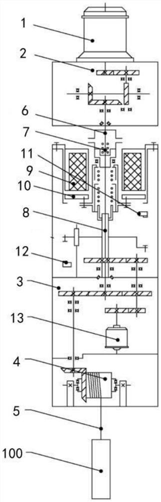
[0047] A control rod driving device for an open reactor includes a driving motor 1 , an upper speed reducer 2 , a brake assembly, a lower speed reducer 3 , a winch 4 and a wire rope 5 .

[0048] The torque input end of the upper reducer 2 is connected with the torque output end of the driving motor 1;

[0049] The torque input end of the brake assembly is connected to the torque output end of the upper reducer 2;

[0050] The torque input end of the lower reducer 3 is connected with the torque output end of the brake assembly;

[0051] The upper reducer 2 and the lower reducer 3 can adopt the existing reducer at the present stage. The reducer is an independent component composed of a gear drive, a worm drive, and a gear-worm drive enclosed in a rigid shell. It is often used as the original The reduction transmission device between the moving part and the working machine. It plays the role of matching speed and transmitting torque between prime mover and working machine or ac...

Embodiment 2

[0058]The structure in the first embodiment realizes the driving of the control rods 100, so that it can be installed in an open reactor, but if a power failure occurs, the rods need to be dropped automatically quickly to improve safety, which is realized by the brake assembly. Yes, the brake assembly includes an upper friction plate 6, a lower friction plate 7, a brake spindle 8 and a safety control assembly.

[0059] The upper friction plate 6 is arranged horizontally, and the rotating shaft of the upper friction plate 6 is fixedly connected with the torque output shaft of the upper reducer 2;

[0060] The lower friction plate 7 is arranged below the upper friction plate 6, and is coaxial and parallel to the upper friction plate 6;

[0061] The outer surface of the brake main shaft 8 is provided with an axial key, and the lower friction plate 7 is provided with a keyway adapted to the key, and the lower friction plate 7 is axially slidably connected with the brake main shaft...

Embodiment 2

[0075] For the second embodiment, in order to prevent the braking main shaft 8 from moving up or down too long and causing damage to the entire driving device, the safety control assembly also includes an upper limit assembly 11 and a lower limit assembly 12 .

[0076] The upper limit assembly 11 is arranged below the assembled armature 10, and when it is in working condition, when the control rod 100 falls to the set minimum position, the upper limit assembly 11 sends a control signal to the control motor 1, and The control motor 1 is stopped, which prevents the control motor 1 from continuously idling.

[0077] The lower limit assembly 12 is arranged above the lower reducer 3. When the control rod 8 is lifted to the set highest position, the lower limit assembly 12 sends a control signal to the control motor 1, and stops the control motor 1, avoiding the control motor 1 continuous idling.

[0078] Both the upper limit assembly 11 and the lower limit assembly 12 in this embo...


PUM


Abstract

The invention discloses a control rod driving device of an open reactor, which comprises a driving motor, an upper speed reducer, a brake assembly, a lower speed reducer, a winding drum and a steel wire rope, and the torque input end of the upper speed reducer is connected with the torque output end of the driving motor; the torque input end of the brake assembly is connected with the torque output end of the upper speed reducer; the torque input end of the lower speed reducer is connected with the torque output end of the brake assembly; a rotating shaft of the winding drum is connected with a torque output end of the lower speed reducer; the upper speed reducer and the lower speed reducer are used for reducing the output rotating speed of the driving motor, the first end of the steel wire rope is fixedly connected with the winding drum, the steel wire rope is wound on the winding drum, and the control rod is fixedly connected with the second end of the steel wire rope. The length of the steel wire rope is shortened through the winding drum, the position of the control rod is adjusted, most parts are easy to machine, and the structure is simple.

Description

technical field [0001] The invention relates to the field of nuclear reactor control, in particular to a control rod driving device for an open reactor. Background technique [0002] In the working state of the open reactor, the control rods need to be placed in the open reactor, and the following functions need to be realized: the control rods can run freely within the full driving stroke range, the rods can be held reliably, and the control rod driving mechanism is not allowed. Unable to lift rods, out of step, stuck rods caused by other reasons; the shutdown function can be performed within the range of equipment operating conditions, and the control rods at any stroke position or in the process of lifting and lowering should be able to perform emergency shutdown and drop rods, Sticking rods and sticking rods due to the driving mechanism of the control rods are not allowed. [0003] At present, most of the control rod driving devices have complex structures. At the same ...

Claims


Application Information

Patent Timeline
Patent Type & Authority Applications(China)
IPC IPC(8): G21C7/14
CPCG21C7/14Y02E30/30
Inventor 罗有为袁志敏向玉新操节宝王皓熊俊梁光远李海涛贾亚青葛源偶建磊
Owner NUCLEAR POWER INSTITUTE OF CHINA
Why Eureka
Try Eureka