Stress relieving device for spiral forming of reinforcing steel bars

A steel helix and stress relief technology is applied in the application of steel bar stress relief devices and in the field of stress relief devices for steel bar helix forming. Efficiency and precision, easy transportation and sorting, high degree of automation

Active Publication Date: 2021-01-29
安徽德基汇金机械科技有限公司
View PDF12 Cites 0 Cited by
  • Summary
  • Abstract
  • Description
  • Claims
  • Application Information

AI Technical Summary

Problems solved by technology

[0004] The purpose of the present invention is to solve the problem that the existing stress-relief device has a low degree of automation for steel bar stress-relief processing, and the operation and use are very cumbersome; stress-relief treatment for steel bars; and the existing stress-relief device cannot quickly adjust the position occupied indoors, and its use is very limited; when the stress-relief device is used for stress-relief treatment of steel bars, the steel bars are easy to scrape against the components on the device and cause damage, the stress relief device has poor stability for the stress relief of the steel bars; and after the stress relief device has completed the stress relief of the steel bars, the steel bars cannot be uniformly transported to the same position, which is not convenient for the staff to arrange and transport the stress relieved steel bars , and a stress relief device for spiral forming of steel bars is proposed

Method used


Image

  • Stress relieving device for spiral forming of reinforcing steel bars
  • Stress relieving device for spiral forming of reinforcing steel bars
  • Stress relieving device for spiral forming of reinforcing steel bars

Examples


Embodiment Construction

[0044] The technical solutions of the present invention will be clearly and completely described below in conjunction with the embodiments. Apparently, the described embodiments are only some of the embodiments of the present invention, not all of them. Based on the embodiments of the present invention, all other embodiments obtained by persons of ordinary skill in the art without creative efforts fall within the protection scope of the present invention.

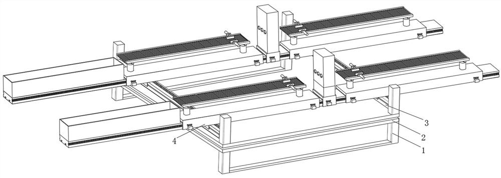
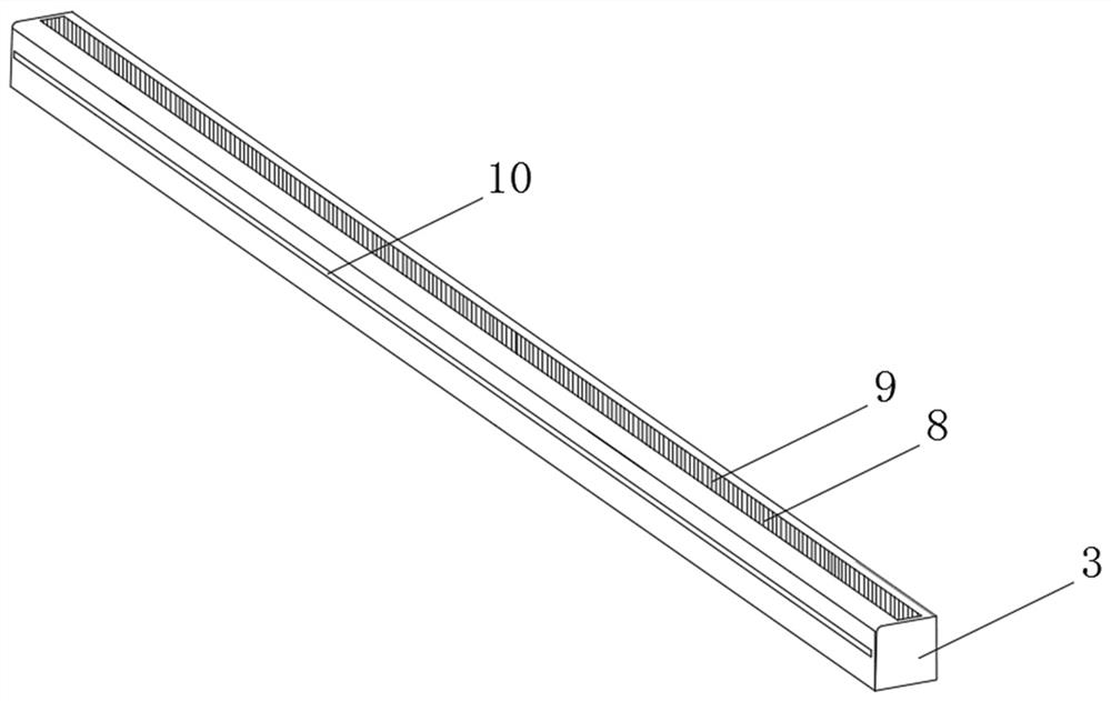
[0045] see Figure 1-12 As shown, a stress relief device for spiral forming of steel bars includes a base 1, an inner rotation table 2 and several transport racks 4, the inner rotation table 2 is located above the base 1, and both ends above the inner rotation table 2 are arranged There are rolling frames 3, and a number of transport racks 4 are arranged above the two rolling frames 3;

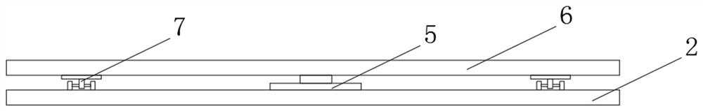
[0046] Wherein, the middle part of the internal rotation table 2 is provided with a motor one 5, and the top of the motor one 5 is connec...


PUM


Abstract

The invention discloses a stress relieving device for spiral forming of reinforcing steel bars. The stress relieving device comprises a base, an inner rotary table and multiple transporting and loading frames. The inner rotary table is located above the base, rolling frames are arranged at the two ends of the upper portion of the inner rotary table, the multiple transporting and loading frames arearranged above the position between the two rolling frames, a first motor is arranged in the middle of the inner rotary table, and a rotating plate is rotationally connected above the first motor. The stress relieving device for spiral forming of the reinforcing steel bars has the beneficial effects that a gas stove burns gas to heat the reinforcing steel bars, stress in the reinforcing steel bars is slowly eliminated, the later-period use precision of the reinforcing steel bars is improved, when the reinforcing steel bars almost completely pass through a thermal aging furnace, one ends of the reinforcing steel bars fall onto a crawler belt of the other supporting and conveying mechanism of each transporting and loading frame, the crawler belts drive the reinforcing steel bars to move close to falling boxes, and finally, the reinforcing steel bars fall into the falling boxes to be stored. According to the device, the automation degree of reinforcing steel bar stress relieving work ishigher, the device is quite time-saving and labor-saving to use, the reinforcing steel bars subjected to stress relieving can fall into the falling boxes in a unified mode to be stored, and workers can transport and arrange the reinforcing steel bars in a unified mode conveniently.

Description

technical field [0001] The invention relates to a stress relief device, in particular to a stress relief device for spiral forming of steel bars, and belongs to the application technical field of stress relief devices for steel bars. Background technique [0002] With the rapid development of science and technology, the stress relief device is used more and more frequently in the process of steel bar processing. After the steel bar is spirally formed, the steel bar is placed in a thermal aging furnace for heat treatment through the stress relief device, and the stress is gradually eliminated. Improve the accuracy of the steel bar in the later use, and avoid the bending of the steel bar in the later stage. [0003] The existing stress relief devices for spiral forming of steel bars still have great defects in use. The existing stress relief devices have a low degree of automation for the stress relief of steel bars, and the operation and use are very cumbersome. The flexibil...

Claims


Application Information

Patent Timeline
IPC IPC(8): C21D9/56C21D1/34
CPCC21D9/0018C21D9/56C21D1/34
Inventor 刘新贺彭保臣
Owner 安徽德基汇金机械科技有限公司
Why Eureka
Try Eureka