Method for determining an electron density distribution in the earth's atmosphere

A technology of electron distribution and atmosphere, applied in the direction of radio wave measurement system, satellite radio beacon positioning system, instrument, etc., can solve the problems of large distance and low resolution of TEC data

Active Publication Date: 2019-10-01
ROBERT BOSCH GMBH
View PDF4 Cites 1 Cited by
  • Summary
  • Abstract
  • Description
  • Claims
  • Application Information

AI Technical Summary

Problems solved by technology

However, the resolution of the TEC data thus determined is therefore very low due to the small number of corresponding reference stations and the large distance between the stations

Method used


Image

  • Method for determining an electron density distribution in the earth's atmosphere
  • Method for determining an electron density distribution in the earth's atmosphere
  • Method for determining an electron density distribution in the earth's atmosphere

Examples


Embodiment Construction

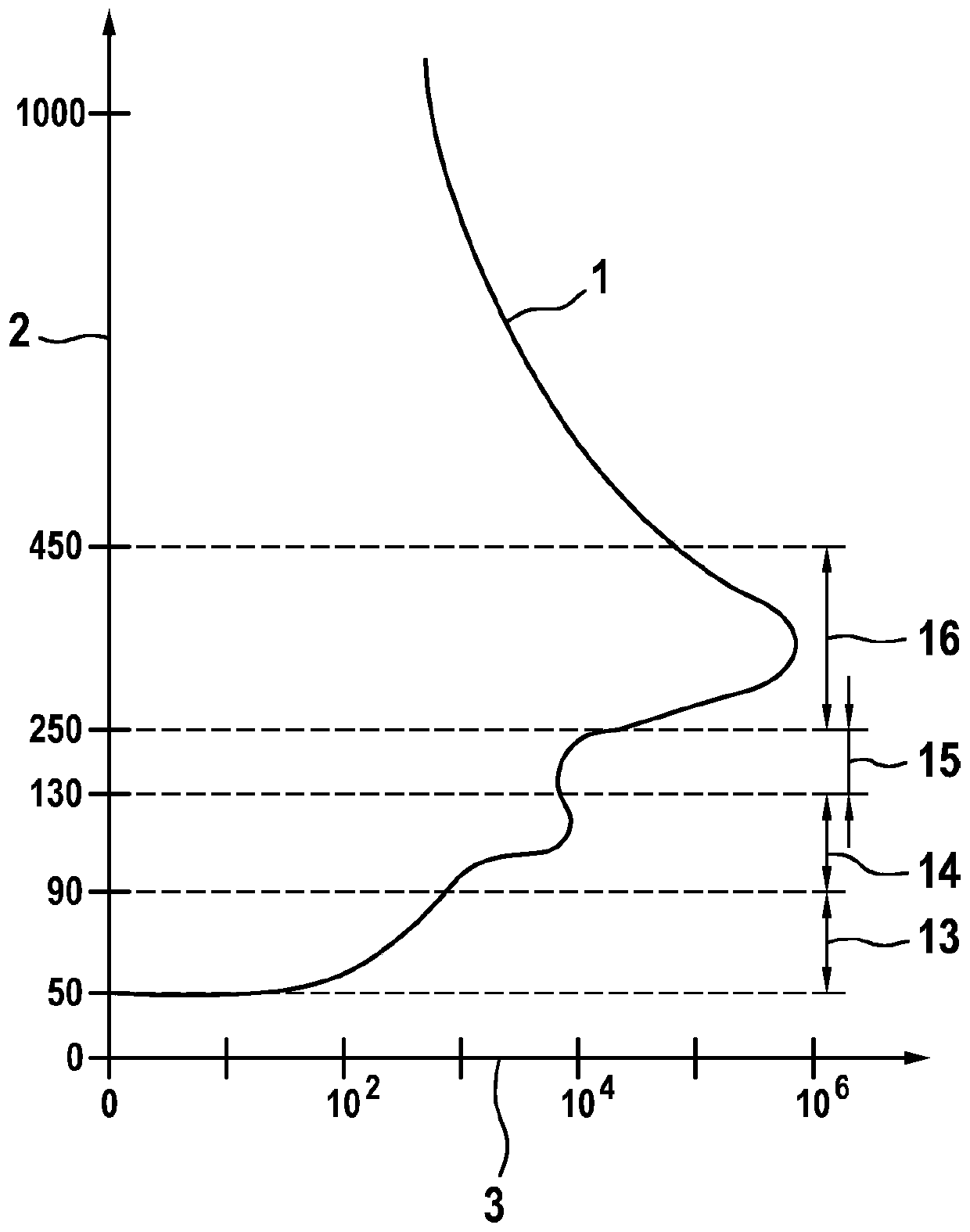
[0036] figure 1 A diagram of the electron density distribution 1 of the ionosphere is schematically shown. Plot electron density 3 on the axis of abscissa, in units of electrons per cubic centimeter, and plot height 2 on the axis of ordinate, in units of kilometers. Depending on electron density and height, the layers D layer 13 , E layer 14 , F1 layer 15 and F2 layer 16 are different. It can be seen that the electron density is greatest in the F2 layer 16 and thus the F2 layer 16 has the greatest influence on signal propagation through the ionosphere.

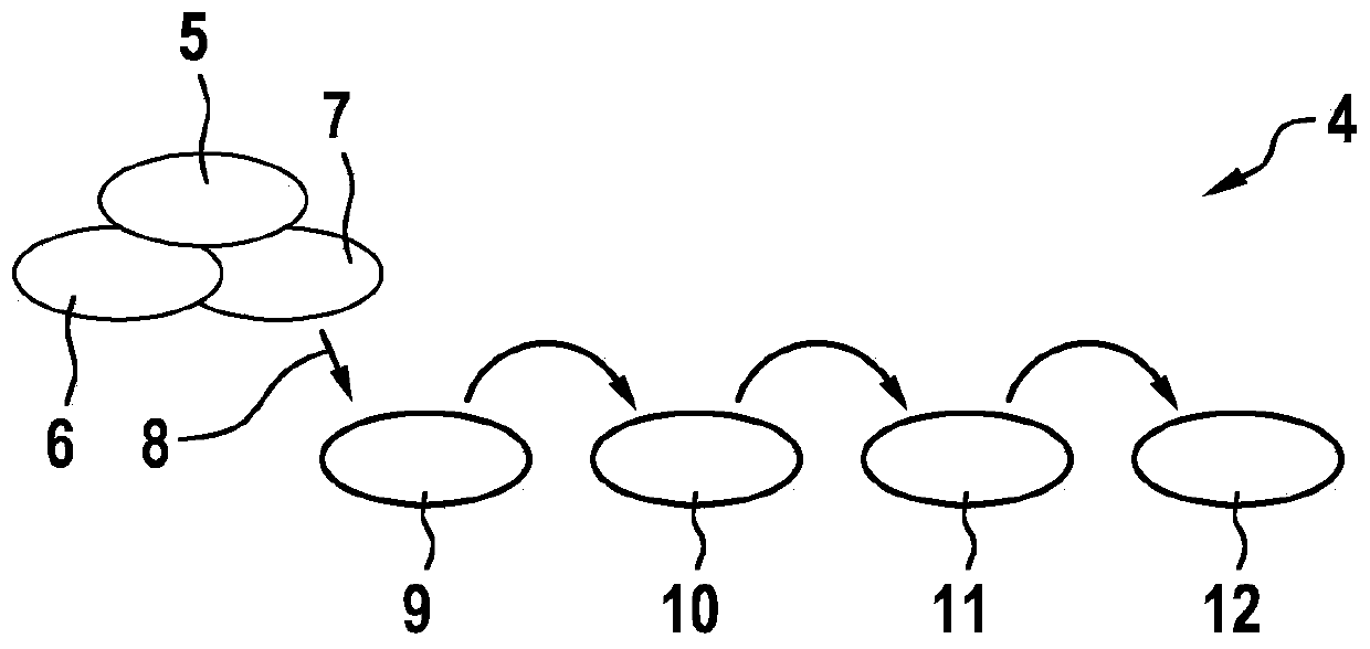
[0037] figure 2 An exemplary model structure of the ionospheric model 4 is schematically shown, in which the method proposed here is used. In this case, the method is used, for example, to determine the electron density distribution in the ionosphere, wherein the altitude-dependent electron density is also used to determine the (position-dependent) TEC. figure 2 In this regard, the relationship between the individual cal...


PUM


Abstract

The invention relates to a method for determining a four-dimensional ionosphere model of an electron distribution in the Earth's atmosphere, which is used to correct runtime measurements of signals emitted by satellites, for position determinations by means of signal receivers, comprising at least the following steps: a) defining at least one distribution function based on at least one function parameter which is suitable to describe a distribution of electrons over the height of the Earth's atmosphere, b) receiving data from a plurality of runtime measurements by means of a plurality of movable dual-frequency signal receivers, in order to determine parameters that are representative for a total quantity of electrons along a signal transmission path from a satellite to a dual-frequency signal receiver, c) determining location-dependent and time-dependent function parameters for the distribution function at least by means of the parameters, d) providing the function parameters determined in step c) as a four-dimensional ionosphere model.

Description

technical field [0001] The invention relates to a method for determining the electron density distribution in the Earth's atmosphere. Background technique [0002] The ionosphere is described as a region of the (high) Earth's atmosphere that extends approximately between 50km and 1000km altitude and enters the plasmasphere above. The ionosphere is characterized by an increased concentration of charged particles, such as ions and free electrons, which are produced by ionization processes dependent on solar radiation. Depending on the frequency and strength of the ionization, electromagnetic signals in the ionosphere are refracted. Signal delays thus arise in the observations of Global Navigation Satellite Systems (GNSS), for example the American GPS system or the European Galileo, which are a major source of error in positioning and navigation applications. When using expensive, geodesic dual-frequency receivers, signal combining can be used to eliminate primary ionospheric...

Claims


Application Information

Patent Timeline
Patent Type & Authority Applications(China)
IPC IPC(8): G01S19/07G01S19/08
CPCG01S19/08G01S19/072
Inventor M·朗格尔M·林贝格尔
Owner ROBERT BOSCH GMBH
Why Eureka
Try Eureka