

Grinding method and grinding device of workpiece
A grinding method and technology for workpieces, which are applied in grinding devices, grinding machine tools, manufacturing tools, etc., can solve the problems of poor platform torque response, difficulty in grasping the correlation of torque wafers, and inability to detect the grinding amount, so as to improve productivity and prevent Bad chip effect
- Summary
- Abstract
- Description
- Claims
- Application Information
AI Technical Summary
Problems solved by technology
Method used
Image

Examples
Embodiment 1
[0117] In order to clarify the effect of the present invention, an experiment was performed to evaluate the relationship between the temperature phase of the carrier and the thickness and shape of the wafer while changing the polishing time.
[0118] The grinding time was set at five levels in which the grinding time was changed between 29 and 32 minutes.
[0119] In the test, a p-type silicon wafer with a diameter of 300 mm and crystal orientation (100) was used as the wafer to be polished.
[0120] As the carrier plate, a plate of glass fiber reinforced plastics (GFRP: Glass Fiber Reinforced Plastics) obtained by compounding glass fibers in epoxy resin with an initial thickness of 745 μm was used.
[0121] Here, the center of the wafer and the center of the carrier plate were eccentric by 30 mm.
[0122] use Figure 6 For the device having the structure shown in (a), foamed polyurethane polishing cloth MHN15 manufactured by Nitta Haas Incorporat ed. was used for the polish...
Embodiment 2
[0132] The same test as in Example 1 was performed except having changed the grinding time to five levels of "30, 35, 40, 45, and 50 (min)".
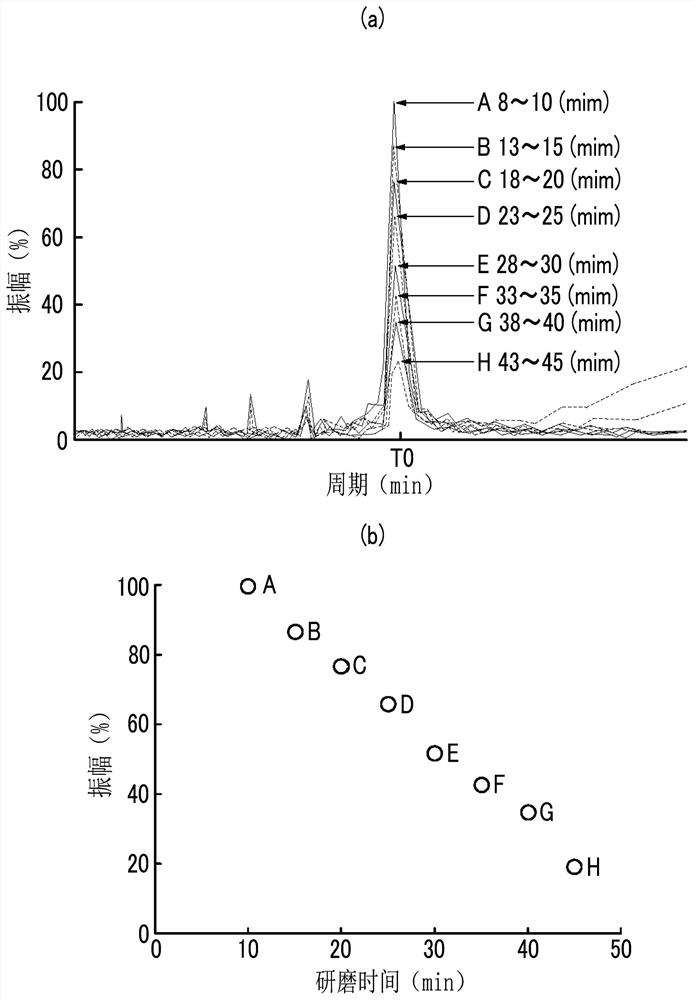
[0133] Figure 12 shows the results of the carrier plate vibration at the end of each level of polishing for which the polishing time was changed. In addition, in Figure 12 In , the amplitude at the end of polishing on the vertical axis is represented by a relative value when the amplitude at the end of polishing when the polishing time is 30 min is set to 100.
[0134] and, Figure 13 2 shows the relationship between the amplitude at the end of polishing and the thickness of the wafer, and the relationship between the amplitude and the above-mentioned SFQR in the vicinity of the outer peripheral portion of the wafer.
[0135] In addition, in Figure 13 In the figure, the SFQR on the vertical axis and the amplitude at the end of polishing on the horizontal axis are expressed as relative values when the SFQR at the end of polishin...
Embodiment 3
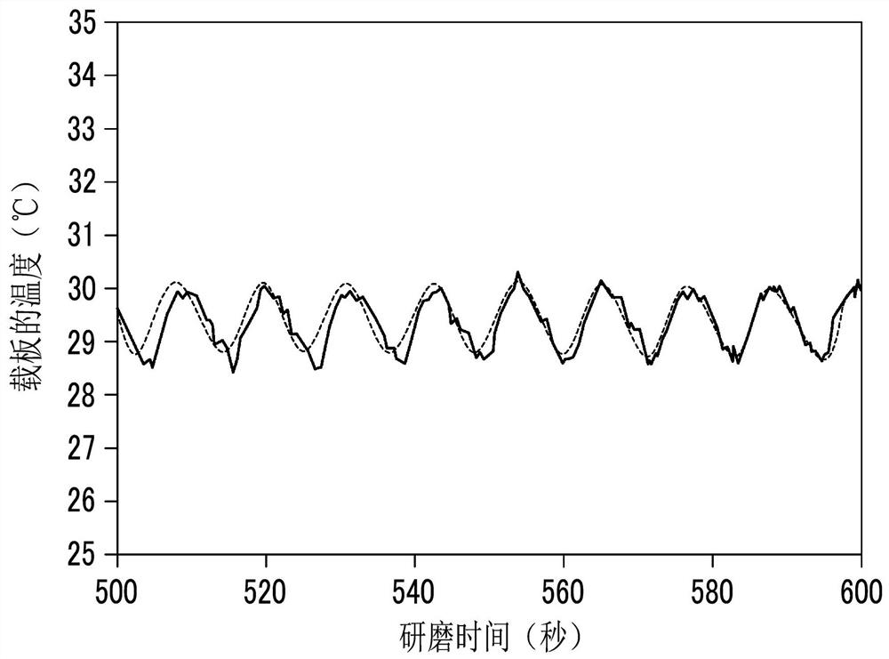
[0140] In order to confirm that the effect of the present invention is effective regardless of the material of the carrier, a test was conducted to evaluate the relationship between the polishing time and the temperature amplitude of the carrier using three types of carriers with different materials.
[0141] The three types of materials were assumed that the carrier was made of GFRP, the carrier made of GFRP was coated with diamond-like carbon, and the carrier made of SUS was coated with diamond-like carbon.
[0142] The test is set as follows to carry out: (1) the initial thickness of the support plate made of GFRP is 745 μm, and the grinding time is 30 minutes; (2) the initial thickness of the support plate coated with diamond-like carbon on the support plate made of GFRP is 746 μm, and the polishing time was 32 minutes; (3) The initial thickness of the support plate coated with diamond-like carbon on the SUS support plate was 754 μm, and the polishing time was 34 minutes. ...
PUM
 Abstract
Description
Claims
Application Information