
Impeller assembly

A technology of components and pulsators, applied in the field of clothing treatment, can solve problems such as the inability to improve the detergent dissolution effect

Active Publication Date: 2019-10-08
QINGDAO HAIER WASHING MASCH CO LTD +1
View PDF11 Cites 0 Cited by
  • Summary
  • Abstract
  • Description
  • Claims
  • Application Information

AI Technical Summary

Problems solved by technology

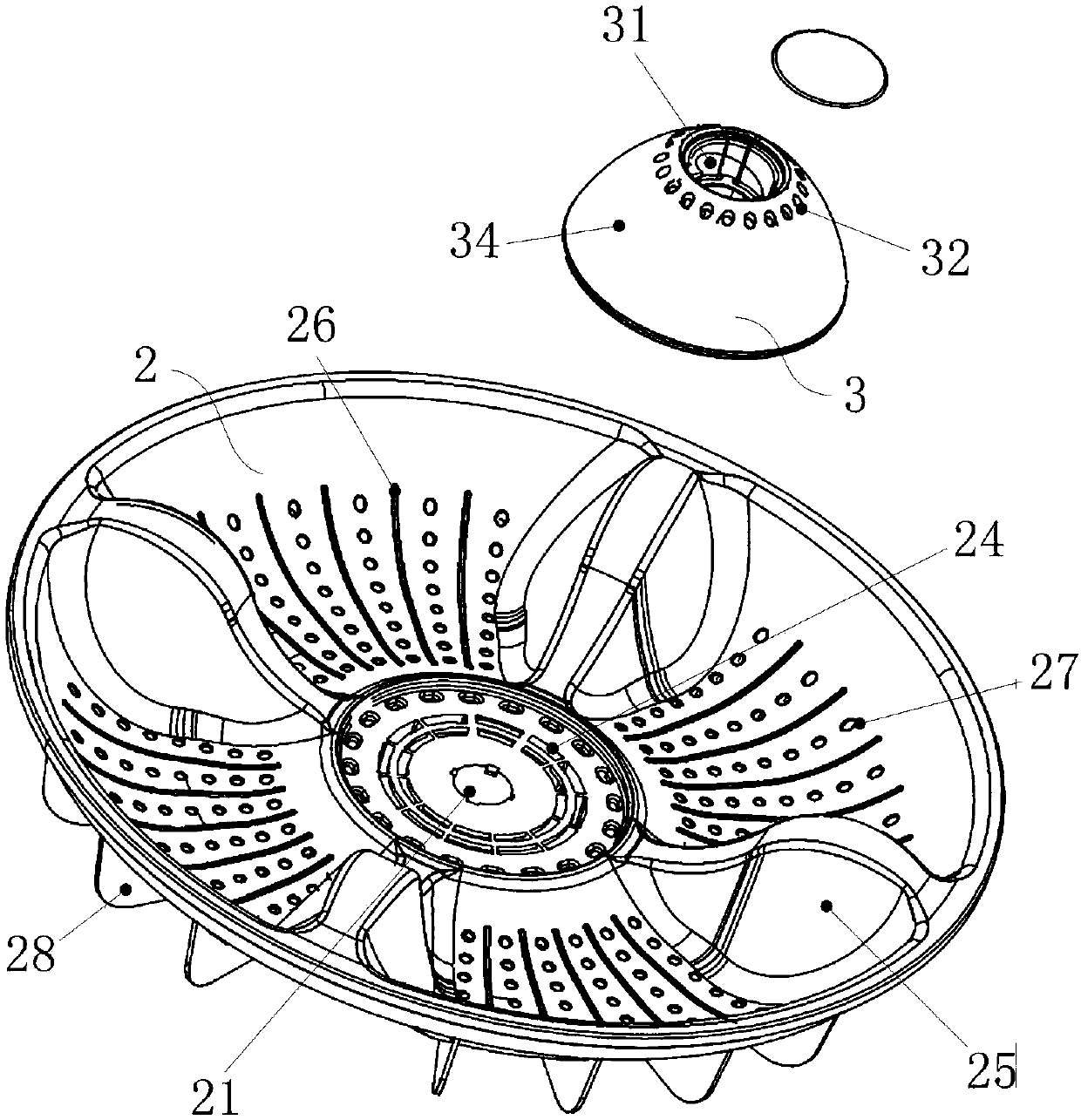
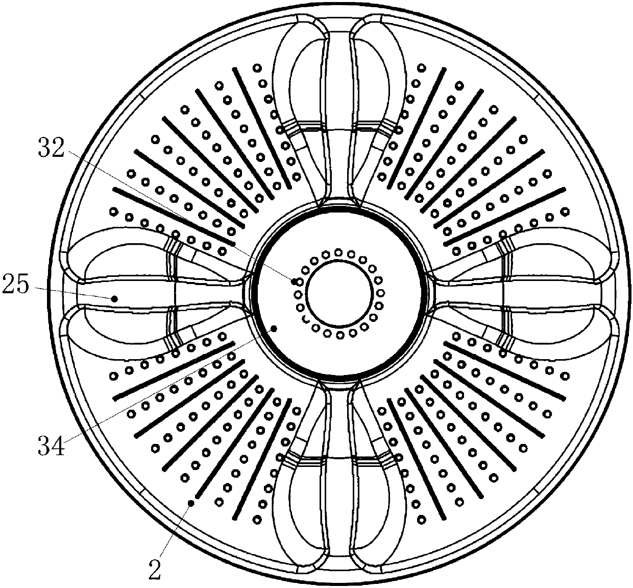
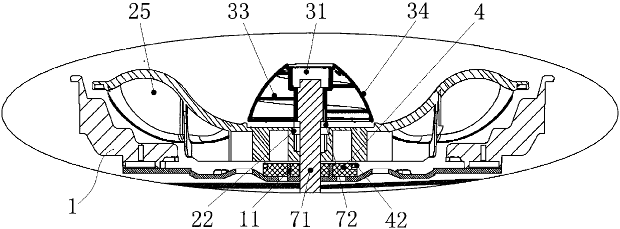
[0005] In order to solve the above-mentioned problems in the prior art, that is, in order to solve the problem that the existing washing machine pulsator cannot improve the dissolving effect of detergent in water, the present invention provides a pulsator assembly, which includes an inner tub bottom, a set The first wheel above the bottom of the inner bucket, the runner set above the first wheel, and the buoyancy unit set between the bottom of the inner barrel and the first wheel, the first wheel A through hole is provided in the center of the center, and the first disc is slidably sleeved on the transmission shaft of the driving device through the through hole, and the runner is provided with a shaft hole, and the runner passes through the shaft hole It is connected with the transmission shaft; the first wheel is provided with a first meshing structure, and the transmission shaft and / or the running wheel is correspondingly provided with a second meshing structure, and the bottom of the inner bucket is also provided with a useful As a guide structure for limiting and guiding the buoyancy unit, when the buoyancy unit moves upward under the action of buoyancy and pushes the first wheel to move upward, the first engaging structure and the second The engaging structure is engaged so that the first wheel can rotate driven by the transmission shaft

Method used


Image

  • Impeller assembly
  • Impeller assembly
  • Impeller assembly

Examples


Embodiment Construction

[0025] Preferred embodiments of the present invention are described below with reference to the accompanying drawings. Those skilled in the art should understand that these embodiments are only used to explain the technical principles of the present invention, and are not intended to limit the protection scope of the present invention. For example, although there are four first water-repelling blades arranged on the first disc in the drawings, this quantitative relationship is not static, and those skilled in the art can make adjustments to suit specific applications. For example, three or five first water-repelling leaves can also be arranged on the first wheel, so as to improve the washing effect in different application scenarios.

[0026] It should be noted that, in the description of the present invention, the terms "center", "upper", "lower", "left", "right", "vertical", "horizontal", "inner", "outer" etc. The terms of the indicated direction or positional relationship ...


PUM


Abstract

The invention relates to the technical field of clothes treatment, in particular to an impeller assembly. The invention aims to solve the problem that an existing washing machine impeller cannot improve the dissolving effect of detergent in water. For solving the problem, the impeller assembly comprises an inner barrel bottom, a first wheel disc, a rotating wheel and a buoyancy unit, wherein a through hole is formed in the center of the first wheel disc, the first wheel disc is vertically slidably arranged on a transmission shaft of a driving device in a sleeving manner through the through hole, and the rotating wheel is provided with a shaft hole and is connected with the transmission shaft through the shaft hole; the first wheel disc is provided with a first meshing structure, the transmission shaft and / or the rotating wheel are correspondingly provided with a second meshing structure, the inner barrel bottom is also provided with a guide structure for limiting and guiding the buoyancy unit, and when the buoyancy unit moves upwards under the action of buoyancy and pushes the first wheel disc to move upwards, the first meshing structure is meshed with the second meshing structure.Through the arrangement mode, the dissolving effect of the detergent in water can be obviously improved, so that the cleanliness is improved.

Description

technical field [0001] The invention relates to the technical field of clothes treatment, in particular to a pulsator assembly. Background technique [0002] The washing machine is a clean electrical appliance that uses electric energy to wash clothes. With the acceleration of the pace of life and people's high requirements for living comfort, the washing machine has become an indispensable household appliance in people's daily life. Taking the pulsator washing machine as an example, the pulsator washing machine relies on the friction between the motor-driven pulsator and the clothes during the forward and reverse process to wash the clothes. However, this washing method has problems such as single water flow and low cleaning degree in the actual washing process. , greatly affecting the user experience. [0003] To solve the above-mentioned problems of the pulsator washing machine, in the prior art, the structure of the pulsator is usually improved or a small pulsator that ...

Claims


Application Information

Patent Timeline
Patent Type & Authority Applications(China)
IPC IPC(8): D06F17/10
CPCD06F17/10Y02B40/00
Inventor 赵志强吕佩师
Owner QINGDAO HAIER WASHING MASCH CO LTD
Learn More