
Reentry vehicle speed-height reentry corridor prediction method

A technology for re-entry aircraft and re-entry corridors, applied in the field of speed-altitude re-entry corridor prediction of re-entry aircraft, speed-altitude boundary prediction of re-entry aircraft, and can solve the problem of not being able to obtain the upper boundary of re-entry aircraft speed-altitude, etc. problems, to achieve the effect of reducing the observation range, improving the guidance accuracy, and strong maneuverability

Active Publication Date: 2019-10-08
BEIJING INSTITUTE OF TECHNOLOGYGY
View PDF11 Cites 2 Cited by
  • Summary
  • Abstract
  • Description
  • Claims
  • Application Information

AI Technical Summary

Problems solved by technology

That is to say, the existing method cannot obtain the velocity-altitude upper boundary of the re-entry vehicle

Method used

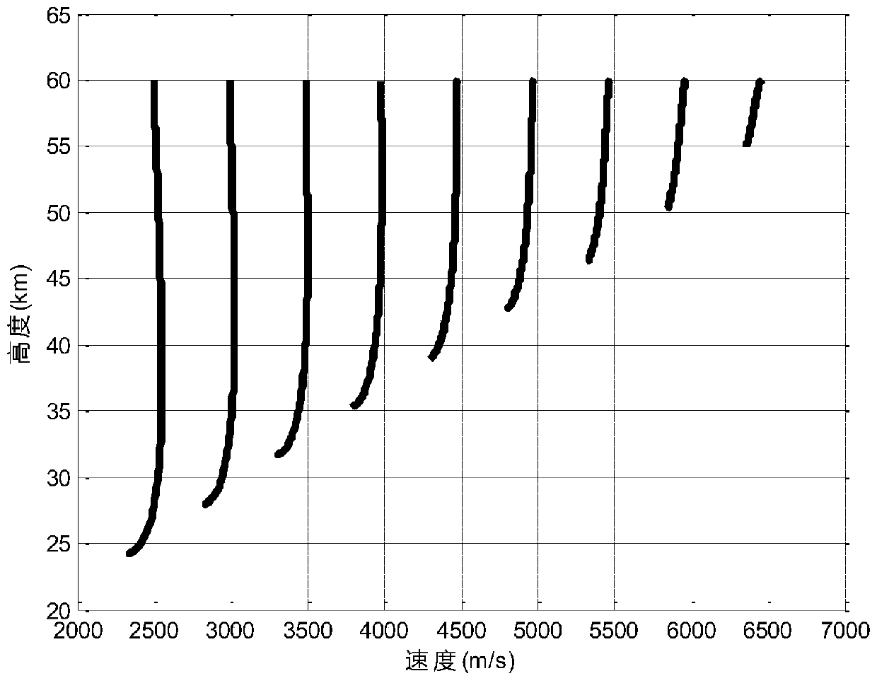
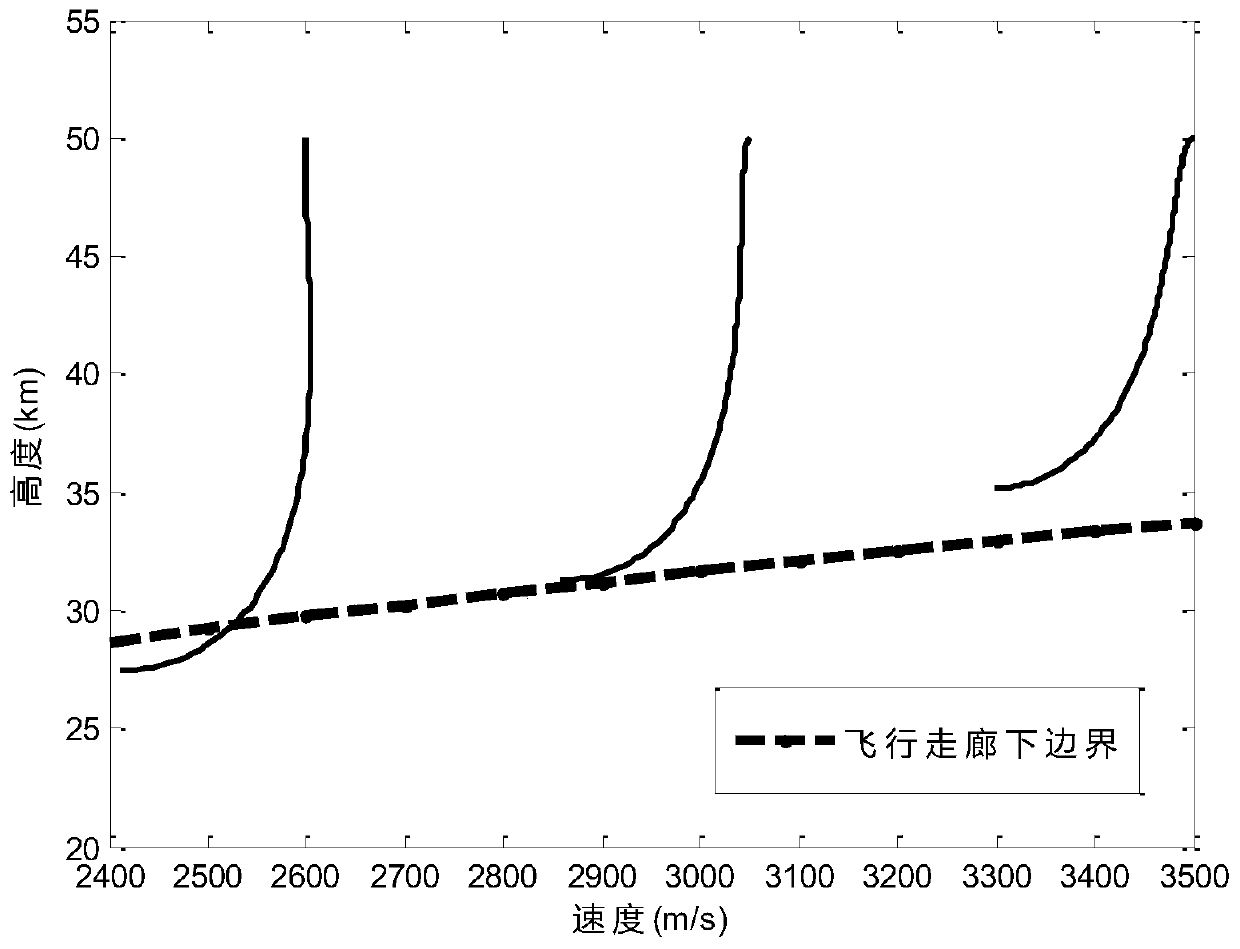
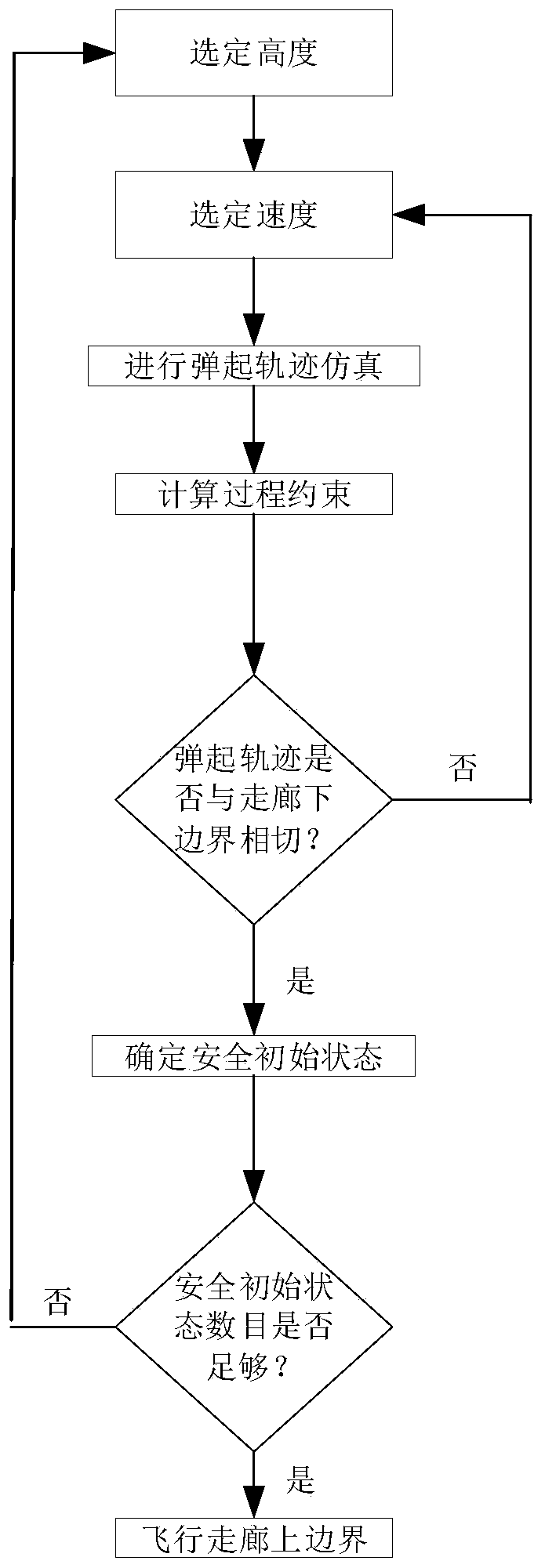

Image

  • Reentry vehicle speed-height reentry corridor prediction method
  • Reentry vehicle speed-height reentry corridor prediction method
  • Reentry vehicle speed-height reentry corridor prediction method

Examples


Embodiment 1

[0050] Taking the CAV-H aircraft model as the object, such as image 3 As shown, a speed-altitude re-entry corridor prediction method for a re-entry aircraft disclosed in this embodiment, the specific implementation steps are as follows:

[0051] Step 1: Establish the dynamic equation of the reentry vehicle.

[0052]

[0053] Among them, v, γ, ψ, r, θ, Φ are velocity, ballistic inclination, ballistic deflection, center of gravity, longitude and latitude respectively; σ is roll angle; ω is earth rotation speed; D and L are drag acceleration and lift acceleration. The formulas for calculating L and D are as follows:

[0054]

[0055] Among them, m is the mass of the aircraft, S A is the aircraft reference area, C L with C D are the lift and drag coefficients of the aircraft, respectively. ρ is the density of the atmosphere, and its calculation formula is as follows:

[0056] ρ=ρ 0 exp(-h / h s ) (11)

[0057] where ρ 0 is the air density at sea level, h is the alt...


PUM


Abstract

The invention discloses a reentry vehicle speed-height reentry corridor prediction method, and belongs to the field of vehicle guidance control. The implementation method comprises the following stepsof establishing a kinetic equation of a reentry vehicle; pre-estimating the lower boundary of a reentry corridor based on the process constraints; realizing the reentry corridor upper boundary estimation based on the reentry vehicle motion characteristics and the process constraints; obtaining the speed-height upper boundary of the reentry vehicle through the strict analysis, namely, reflecting the safety envelope of the reentry process of the vehicle more accurately through the strict reentry corridor, and solving the related engineering problems of the trajectory control of the reentry section of the vehicle by predicting the speed-height reentry corridor of the reentry vehicle, wherein the related engineering problems of the trajectory control of the reentry section of the vehicle include that the guidance precision is improved and the observation range is reduced by designing a reasonable guidance law. Compared with a traditional reentry corridor adopting a quasi-balanced glidingconstraint design, the reentry corridor range is wider, and the characteristics of high maneuvering performance and large trajectory fluctuation range of the reentry vehicle are better met.

Description

technical field [0001] The invention relates to a speed-altitude boundary prediction method of a re-entry aircraft, in particular to a speed-altitude re-entry corridor prediction method of a re-entry aircraft, belonging to the field of aircraft guidance and control. Background technique [0002] Vehicles such as hypersonic glide vehicles and manned spacecraft will be subject to various constraints during re-entry into the atmosphere, such as heat flux constraints, overload constraints, and dynamic pressure constraints. In order to ensure that the aircraft can safely re-enter and return to the earth's surface, the flight trajectory must satisfy these constraints. Engineering often describes these constraints as reentry corridors. The re-entry corridor determines the maneuver range of the vehicle and describes the maneuver envelope of the vehicle. The re-entry corridor design is the basis of the re-entry vehicle trajectory planning, and the design of the flight trajectory in...

Claims


Application Information

Patent Timeline
IPC IPC(8): G06F17/50
CPCG06F2111/04G06F30/15G06F2119/06G06F30/20
Inventor 梁子璇邱宇
Owner BEIJING INSTITUTE OF TECHNOLOGYGY
Features
  • Generate Ideas
  • Intellectual Property
  • Life Sciences
  • Materials
  • Tech Scout
  • Unparalleled Data Quality
  • Higher Quality Content
  • 60% Fewer Hallucinations
Learn More