
Laminator silica gel plate conveying device

A technology of conveying device and silica gel plate, which is applied in the direction of conveyor objects, transportation and packaging, photovoltaic power generation, etc., can solve the problems of waste time and labor of silica gel plate, and achieve the effect of convenient operation, convenient lifting, and convenient disassembly

Pending Publication Date: 2019-10-08
秦皇岛晟成自动化设备有限公司
View PDF0 Cites 0 Cited by
  • Summary
  • Abstract
  • Description
  • Claims
  • Application Information

AI Technical Summary

Problems solved by technology

Such a heavy silicone plate requires at least 4 people to carry and spread the silicone plate in the lamination chamber, and it is time-consuming to replace the silicone plate

Method used


Image

  • Laminator silica gel plate conveying device
  • Laminator silica gel plate conveying device
  • Laminator silica gel plate conveying device

Examples


Embodiment 1

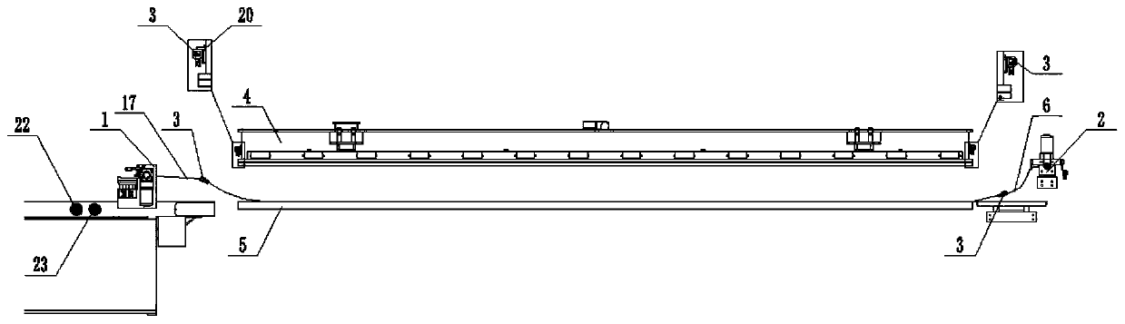
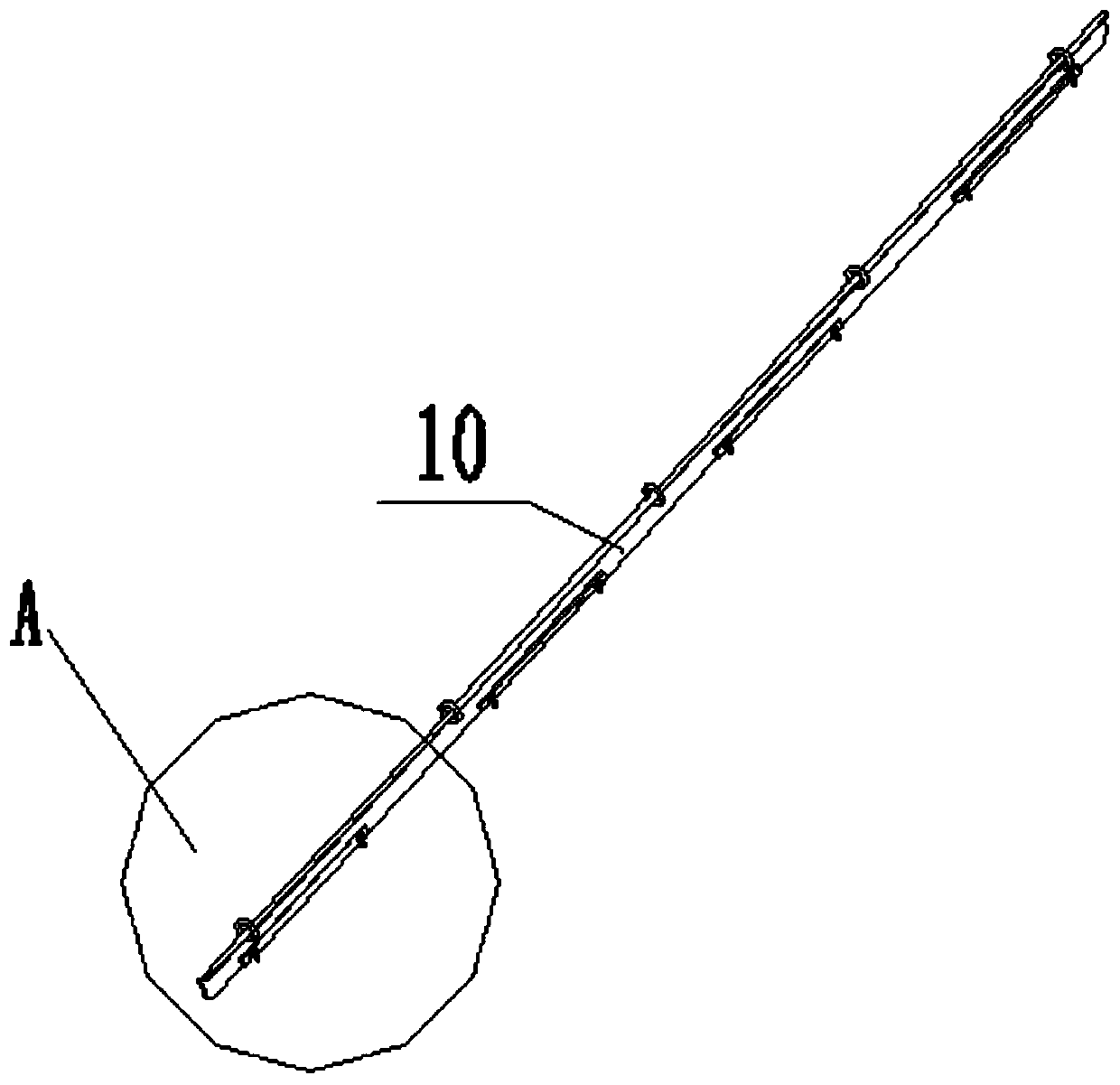
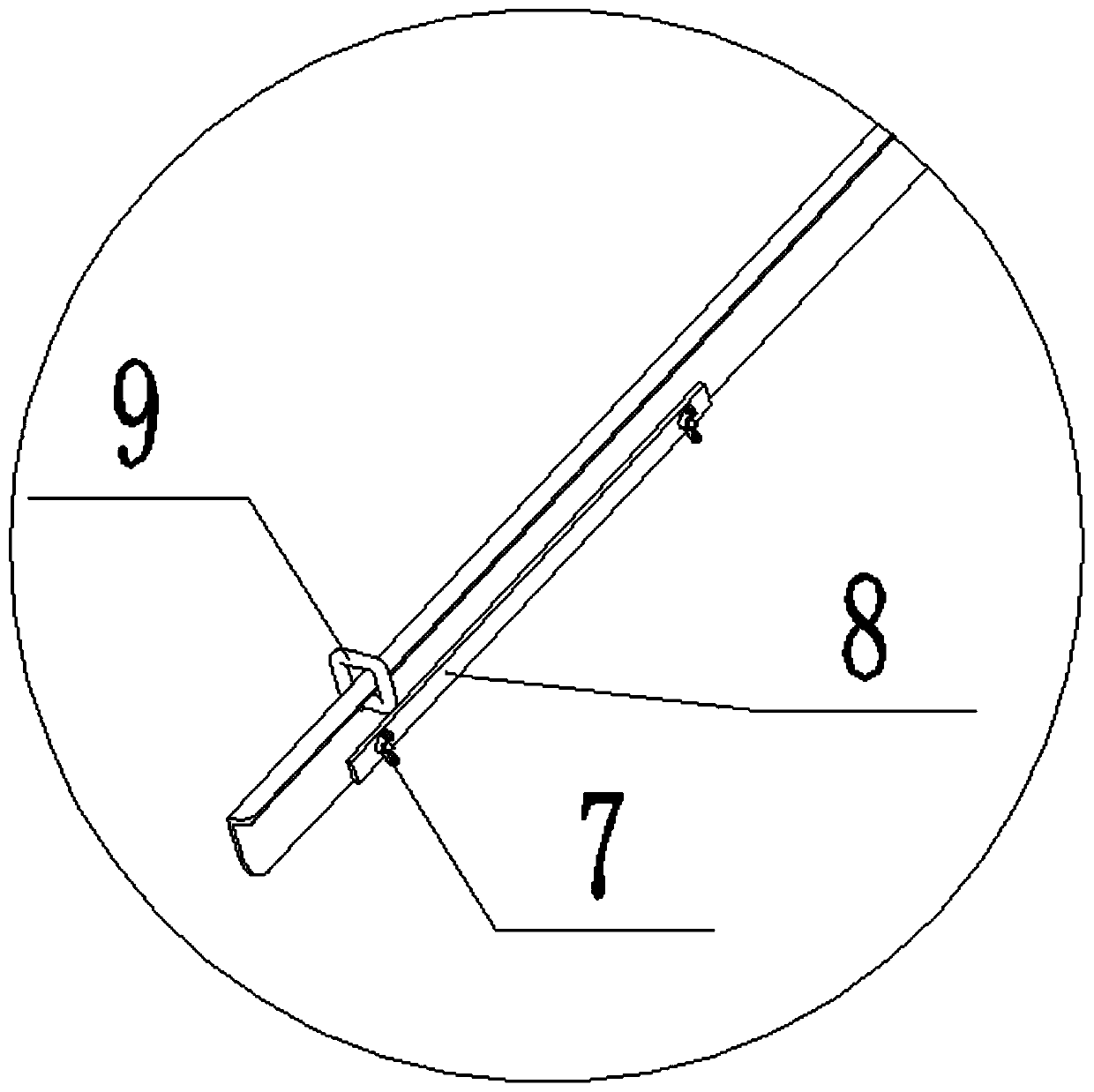
[0021] see Figure 1-4 , a silicone plate conveying device for a laminator, comprising: a waste silicone plate retracting device 1, a new silicone plate pulling device 2, a silicone plate clamping rod 3, a work surface 5 and an upper box 4, and the work surface 5 is arranged on the upper box 4, the two ends of the upper box 4 are provided with silicone plate transverse tie rods 20, and a lamination chamber is formed between the upper box 4 and the work surface 5. The silica gel plate 6 is placed on the worktable 5, and the waste silica gel plate retracting device 1 and the new silica gel plate pulling device 2 are respectively arranged on both sides of the upper box 4. The silica gel plate clamping rod 3 is detachably connected with the waste silica gel plate retracting device 1 and the new silica gel plate pulling device 2 through a steel wire rope 17. The silicone plate clamping rod 3 includes a rotating screw 7 , a pressing plate 8 , a lifting ring 9 and a clamping rod bod...

Embodiment 2

[0025] see Figure 5 , On the basis of Embodiment 1, the new silica gel plate pulling device 2 includes a second drive motor 24, a wire rope winding roller 25, a wire rope guide rod 26, an electromagnetic coupling 27, a seated bearing 28, a bearing mounting plate 29, Mechanism mounting base 30, the mechanism mounting base 30 is installed on the main frame body through bolt connection, the top of the mechanism mounting base 30 is fixed with a bearing mounting plate 29 by bolts, and the two ends of the wire rope winding roller 25 are rotatably connected through the belt seat bearing 28 On the bearing mounting plate 29, the second driving motor 24 is installed on the mechanism mounting seat 30 by bolts, and the electromagnetic coupling 27 is installed in the middle of the wire rope winding drum 25 and the second driving motor 24 through a flat key, for transmitting the second driving motor. Drive the torque of the motor 24, the wire rope guide rod 26 is installed on both sides of...


PUM


Abstract

The invention relates to the technical field of manufacturing a silica gel plate, and particularly discloses a laminator silica gel plate conveying device which comprises a waste silica gel plate recovery device, a new silica gel plate pulling device, a silica gel plate clamping rod, a working table surface and an upper box. The working table surface is arranged below the upper box. The two ends of the upper box are provided with a silica gel plate transverse pulling rod respectively. A laminating chamber is formed between the upper box and the working table surface. The silica gel plate is placed on the working table surface. The waste silica gel plate recovery device and the new silica gel plate pulling device are respectively arranged on the two sides of the upper box. The silica gel plate clamping rod is detachably connected with the waste silica gel plate recovery device and the new silica gel plate pulling device through the steel wire rope. The new and waste silica gel plates can be quickly pulled out of and pulled in the laminating chamber through the waste silica gel plate recovery device and the new silica gel plate pulling device so as to avoid manual pulling, reduce theworkload and improve the working efficiency. The device has the advantages of simple structure, convenient and fast operation, low working intensity, high efficiency and convenient implementation andpopularization.

Description

technical field [0001] The invention relates to the technical field of silica gel plate production, in particular to a silica gel plate conveying device for a laminator. Background technique [0002] When laminating solar cell components, it is necessary to use a silicone plate to laminate the cell components to ensure that the cell components are evenly stressed. However, at present, the use of the silica gel plate is limited to about 10,000 times at most, so the silica gel plate needs to be replaced every once in a while. It is constantly increasing. Taking a double-layer laminator with a lamination area of ​​2.4m×5.8m as an example, the area of ​​the silica gel plate must reach at least 2.6m×6m, and its weight must reach about 110kg. Such a heavy silicone plate requires at least 4 people to carry and spread the silicone plate in the lamination chamber, and it is time-consuming and laborious to replace the silicone plate. Based on the above purpose, the present invention...

Claims


Application Information

Patent Timeline
IPC IPC(8): H01L21/677H01L31/048
CPCH01L31/048H01L21/67742Y02E10/50
Inventor 李硕鹏
Owner 秦皇岛晟成自动化设备有限公司
Learn More