Transceiver, receiving channel and transmitting channel calibration method and device

A technology for transceivers and signal receiving equipment, applied in the field of communication, can solve the problems of complex occupied area of ​​links, etc., and achieve the effect of solving the complex occupied area, reducing the area and reducing the complexity.

Active Publication Date: 2019-10-08
ZTE CORP
View PDF9 Cites 8 Cited by
  • Summary
  • Abstract
  • Description
  • Claims
  • Application Information

AI Technical Summary

Problems solved by technology

[0007] An embodiment of the present invention provides a transceiver, a receiving channel, a calibration method and device for a transmitting channel, a signal transceiving ...

Method used


Image

  • Transceiver, receiving channel and transmitting channel calibration method and device
  • Transceiver, receiving channel and transmitting channel calibration method and device
  • Transceiver, receiving channel and transmitting channel calibration method and device

Examples


Embodiment 1

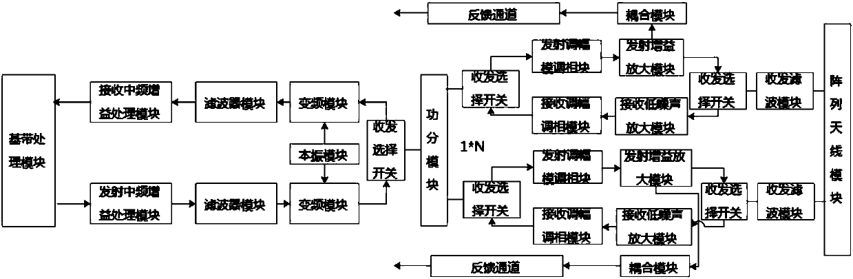
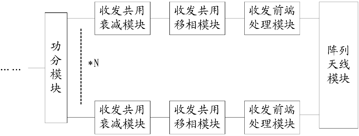
[0054] According to one embodiment of the present invention, a transceiver is provided, including a power dividing module and more than two signal transceiving processing devices, wherein each signal transmitting and receiving processing device includes a transmitting and receiving common attenuation module, a transmitting and receiving common phase shifting module and a transmitting and receiving The front-end processing module, wherein, the transmitting and receiving common attenuation module is connected with the power dividing module, and the transmitting and receiving common attenuating signal is used for attenuating the received or to-be-sent signal; the transmitting and receiving common phase shifting module is connected with the transmitting and receiving common attenuating module, The common phase-shifting module is used to adjust the phase of the received or to-be-transmitted signal; one end of the transceiver front-end processing module is connected to the common phas...

Embodiment 2

[0068] This embodiment mainly describes the calibration method of the receiving channel:

[0069] In this embodiment, a method for calibrating a receiving channel is provided, which can be applied to the transceiver described in Embodiment 1, Figure 7 is a flowchart of a calibration method for a receiving channel according to an embodiment of the present invention, such as Figure 7 shown, including the following steps:

[0070] Step S702, setting the attenuation of the signal transmitting device in one signal transmitting and receiving device to 0, and setting the attenuation of the signal transmitting devices in the other signal transmitting and receiving devices to the maximum value supported by it;

[0071] Step S704: Obtain the phase value of the signal received by the signal receiving device in each signal transmitting and receiving device by controlling the signal transmitting device in one signal transmitting and receiving device to transmit the signal and respective...

Embodiment 3

[0088] This embodiment mainly describes the calibration method of the transmission channel:

[0089] In this embodiment, a transmission channel calibration method is provided, which can be applied to the transceiver described in Embodiment 1, Figure 10 is a flowchart of a method for calibrating a transmission channel according to an embodiment of the present invention, such as Figure 10 shown, including the following steps:

[0090] Step S1002: Set the attenuation of the signal receiving device in one signal transmitting and receiving device to 0, and set the attenuation of the signal receiving device in the other signal transmitting and receiving devices to the maximum value supported by it;

[0091] Step S1004, by controlling the signal transmitting equipment in each signal transmitting and receiving equipment to transmit signals and controlling the signal receiving equipment in one signal transmitting and receiving equipment to receive signals, to obtain the phase values...


PUM


Abstract

The invention provides a transceiver, a receiving channel, a transmitting channel calibration method and device, a signal transceiving system, a storage medium and an electronic device. The transceiver comprises a power division module and more than two paths of signal receiving and transmitting processing equipment, wherein each path of signal transceiving processing equipment comprises a transceiving common attenuation module, a transceiving common phase shift module and a transceiving front-end processing module, wherein the transceiving common attenuation module is connected with a power division module, and the transceiving common attenuation signals are used for performing attenuation processing on received or to-be-sent signals; the transceiving common phase shift module is connected with the transceiving common attenuation module, and is used for adjusting the phase of the received or to-be-sent signal; one end of the transmitting-receiving front-end processing module is connected with the transmitting-receiving common phase shift module, and the other end of the transmitting-receiving front-end processing module is connected with an antenna used for receiving or transmitting signals. Through the method and the device, the problem of complex links and large occupied area of a channel calibration part in the prior art is solved.

Description

technical field [0001] The present invention relates to the communication field, in particular to a transceiver, a receiving channel, a calibration method and device for a transmitting channel, a signal transceiving system, a storage medium and an electronic device. Background technique [0002] The 5th Generation mobile communication technology (referred to as 5G) is proposed in response to the demand for large traffic, including a number of new technologies, including millimeter waves, beam forming, and massive multiple-input multiple-output. MIMO is an important technology of 5G. In order to realize these technical base station hardware links, there are many implementation methods, such as digital beam forming, analog beam forming and digital-analog hybrid beamforming, which are suitable for 5G base stations in terms of cost, area and traffic improvement (for example, 5G millimeter wave base station, the following is referred to as The signal is a millimeter wave signal ...

Claims


Application Information

Patent Timeline
IPC IPC(8): H04B1/40
CPCH04B1/40H04B17/21H04B17/11
Inventor 段亚娟李香玲
Owner ZTE CORP
Why Eureka
Try Eureka