Adjusting limiting mechanism for ultrasonic welding

A technology of ultrasonic welding and limit mechanism, which is applied in the direction of welding equipment, welding equipment, auxiliary welding equipment, etc., which can solve the problems of ensuring equipment, reducing the speed of equipment movement, and reducing the limit accuracy, so as to achieve stable and reliable limit accuracy , does not affect the limit accuracy, and is not easy to deform

Active Publication Date: 2019-10-11
SBT ULTRASONIC TECH CO LTD
View PDF10 Cites 0 Cited by
  • Summary
  • Abstract
  • Description
  • Claims
  • Application Information

AI Technical Summary

Problems solved by technology

[0002] In actual production, sometimes the accuracy of the equipment cannot be guaranteed through machining or the equipment needs to be compatible with a variety of products, and the equipment needs to be adjusted. Due to cost and safety considerations, some equipment can only be adjusted manually. At present, most of the equipment adjustment is through screw adjustment. , which is convenient and can obtain high precision. However, due to the high load and frequency of some equipment, the screw teeth will be deformed due to impact force after long-term use, resulting in lower limit accuracy and even scrapped parts.
In addition, there is also a buffer mechanism before the screw limit to reduce the impact force on the screw, but the buffer mechanism will inevitably reduce the movement speed of the equipment, resulting in a slowdown of the equipment beat, so it is not suitable for high-frequency equipment

Method used


Image

  • Adjusting limiting mechanism for ultrasonic welding
  • Adjusting limiting mechanism for ultrasonic welding

Examples


Embodiment Construction

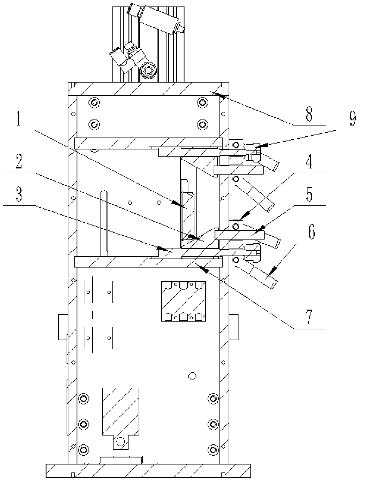
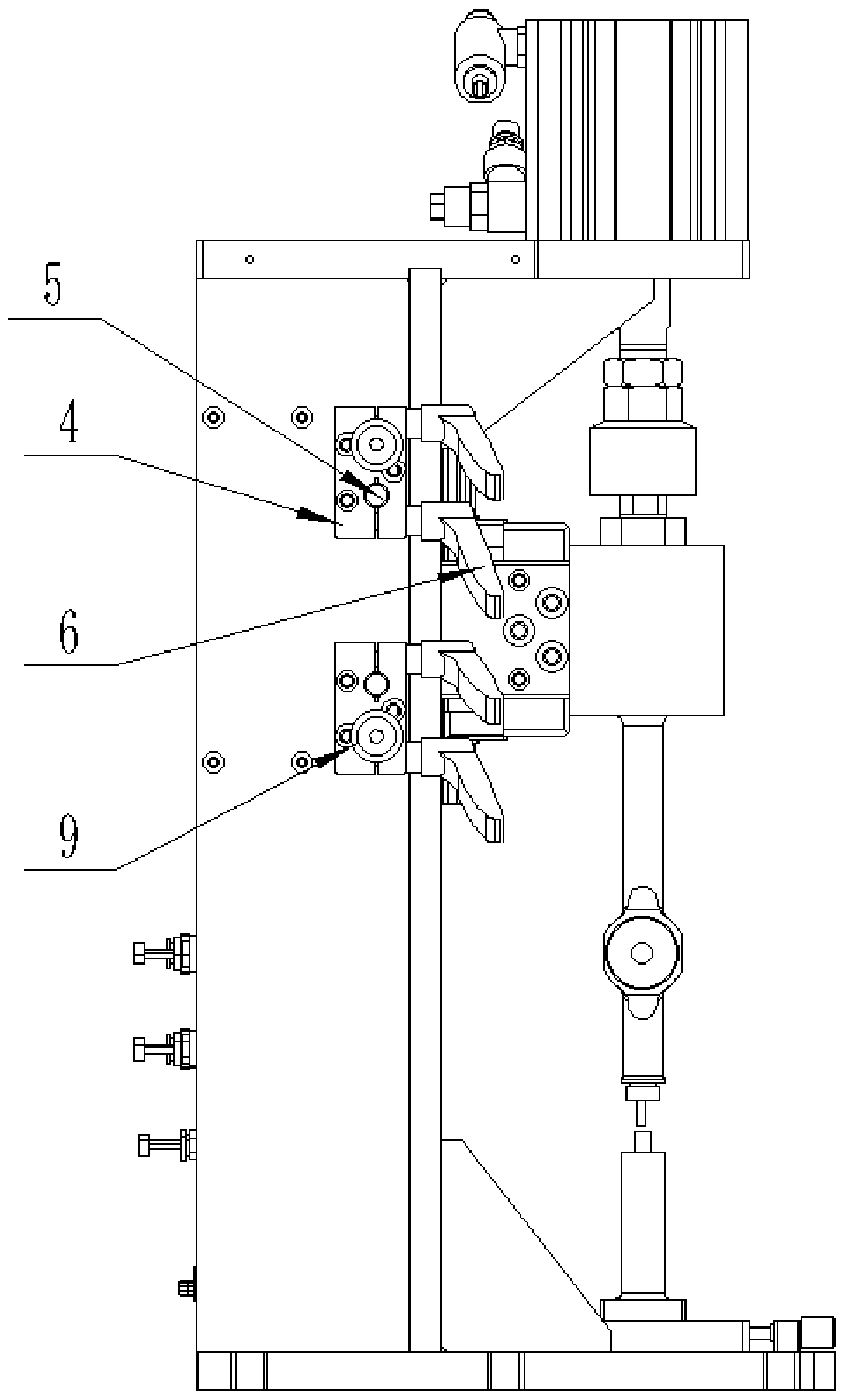
[0013] Such as figure 1 with figure 2 As shown, this specific embodiment adopts the following technical solutions: an adjustment limit mechanism for ultrasonic welding, including a clamp 1, an inclined block 2, a screw rod 3, a hoop 4, an optical axis 5, a handle 6, a pin shaft 7, frame 8 and nut 9; the pin shaft 7 is two, and the pin shaft 7 is arranged at the upper and lower ends of the frame 8; the clamp 1 is located between the pin shafts 7; , The lower two ends are provided with a slanting block 2, and the clamp 1 and the slanting block 2 are slidably connected together; the right side of the slanting block 2 is fixedly connected with an optical axis 5, and the optical axis 5 are all slidingly connected on the frame 8; the outer surface of the optical axis 5 is covered with a hoop 4, and the hoop 4 is located on the outside of the frame 8; the upper and lower sides of the hoop 4 Each end is connected with a handle 6; the hoop 4 is also provided with a screw 3; the righ...


PUM


Abstract

The invention discloses an adjusting limiting mechanism for ultrasonic welding. The adjusting limiting mechanism comprises a clamp, inclined blocks, screw rods, hoops, optical shafts, handles, pin shafts, a machine frame and nuts. According to the adjusting limiting mechanism for the ultrasonic welding, stable and reliable limiting precision can be obtained for high-frequency high-load equipment needing to be adjusted in place, when the clamp reaches a position, the inclined surface of the clamp collides with the inclined surfaces of the inclined blocks, the movement of the clamp is stopped, and the impact force is broken down into into component force in a vertical direction and a horizontal direction by the inclined surfaces of the inclined blocks, the screw rods are directly contacted with the machine frame in the vertical direction, so that the impact force is directly borne by the machine frame; the impact force in the horizontal direction is transmitted to the optical shafts, theoptical shafts are tightly held by the hoops and are fixed on the machine frame, so that the impact force in the horizontal direction is also absorbed by the rack finally; in the whole process, the clamp, the inclined blocks and the optical shafts are in surface contact, so that area of thrust surface is large, deformation is not easy, so that the requirement that the limiting precision is not influenced while the adjusting limiting mechanism is long-term uses is met; and the inclined blocks and the screw rods are connected through fine threads, so that the adjusting precision is ensured.

Description

technical field [0001] The invention relates to the technical field of limit mechanisms, in particular to an adjustment limit mechanism for ultrasonic welding. Background technique [0002] In actual production, sometimes the accuracy of the equipment cannot be guaranteed through machining or the equipment needs to be compatible with a variety of products, and the equipment needs to be adjusted. Due to cost and safety considerations, some equipment can only be adjusted manually. At present, most of the equipment adjustment is through screw adjustment. , which is convenient and can obtain high precision. However, due to the high load and frequency of some equipment, the screw teeth will be deformed due to impact force after long-term use, resulting in lower limit accuracy and even scrapped parts. In addition, there is also a buffer mechanism before the screw limit to reduce the impact force on the screw, but the buffer mechanism will inevitably reduce the movement speed of th...

Claims


Application Information

Patent Timeline
IPC IPC(8): B23K20/10B23K20/26B23K37/04
CPCB23K20/10B23K20/26B23K37/0443
Inventor 周宏建孙松
Owner SBT ULTRASONIC TECH CO LTD
Why Eureka
Try Eureka