An automatic pipe cutting machine

A pipe cutting machine and automatic technology, applied in the field of mechanical processing, can solve the problems of safety impact of workers, difficulty in ensuring cutting accuracy, and difficulty in ensuring cutting quality, etc., to ensure cutting quality, uniform and adjustable feed speed, and good practicability. Effect

Active Publication Date: 2020-06-30
南京涵彩机械有限公司
View PDF6 Cites 0 Cited by
  • Summary
  • Abstract
  • Description
  • Claims
  • Application Information

AI Technical Summary

Problems solved by technology

[0002] In the prior art, when the steel pipe is cut to a specific length, it is usually manually marked first, then the steel pipe is fixed on the cutting machine, and the cutting machine is used to cut according to the marked line. Sharp burrs and flashes are generally polished by a grinder in the prior art, but they will still affect the safety of the staff during the process of handling or secondary processing, and the steel pipe is not fixed effectively during cutting, making it difficult to To ensure the accuracy of cutting, the tool rotates and feeds, and the props are fed manually, which makes the feeding uneven and difficult to guarantee the cutting quality

Method used


Image

  • An automatic pipe cutting machine
  • An automatic pipe cutting machine
  • An automatic pipe cutting machine

Examples


Embodiment Construction

[0026] The present invention will be further described below in conjunction with accompanying drawing:

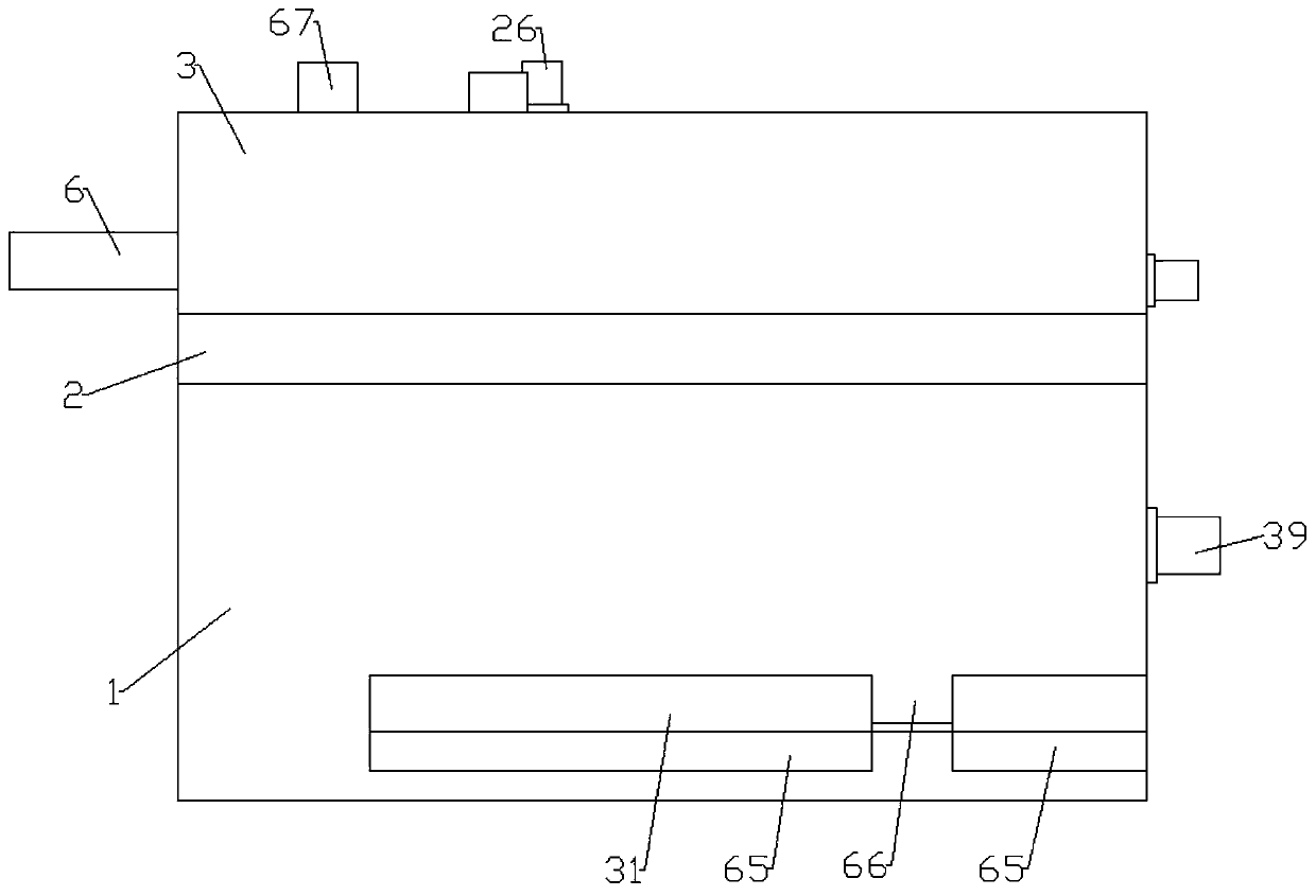
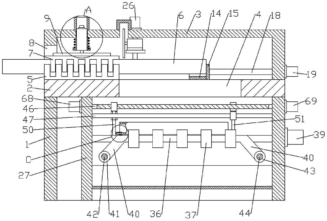
[0027] Refer to attached Figure 1-11 : An automatic pipe cutting machine in this embodiment, comprising a support base 1, the support base 1 is fixedly connected by plates connected end to end, the upper end of the support base 1 is fixedly connected with a working plate 2, and the working plate 2. A sealing cover 3 is fixedly connected to the outer side of the upper end. A blanking opening 4 is opened on the right side of the upper end of the working plate 2. The left end of the blanking opening 4 is provided with a first clamping block 5 fixedly connected to the upper end of the working plate 2. , the upper end of the first clamping block 5 is provided with a steel pipe 6, the upper end of the steel pipe 6 is provided with a second clamping block 7, the left end of the sealing cover is provided with a feed port 8, the first clamping block 5 and The left end of the secon...


PUM


Abstract

The invention relates to an automatic pipe cutting machine. The automatic pipe cutting machine comprises a support base, wherein a working flat board is arranged on the upper end of the support base,a sealing cover is arranged on the outer side of the upper end of the working flat board, a discharging opening is formed in the right side of the upper end of the working flat board, a first clampingblock is arranged on the left end of the discharging opening, a steel pipe is arranged on the upper end of the first clamping block, a second clamping block is arranged on the upper end of the steelpipe, a pressing block is arranged on the upper end of the second clamping block, a hydraulic cylinder is arranged in the center of the upper end of the pressing block, a limiting part is arranged onthe outer side of the lower end of the hydraulic cylinder, a limiting groove is formed in the inner side of the upper end of the limiting part, one end of a compression spring is arranged on the innerside of the limiting groove, a placing part is arranged on the lower side of the right end of the steel pipe, a limiting board is arranged on the right end of the placing part, a first feed screw nutis arranged on the front end of the placing part, a first sliding sleeve is arranged on the back end of the placing part, a first guide rod is arranged on the inner side of the first sliding sleeve,a cutting device is arranged on the upper end of the right side of the second clamping block, and a collecting device is arranged on the inner side of the lower end of the base.

Description

technical field [0001] The invention relates to the technical field of mechanical processing, in particular to an automatic pipe cutting machine. Background technique [0002] In the prior art, when the steel pipe is cut to a specific length, it is usually manually marked first, then the steel pipe is fixed on the cutting machine, and the cutting machine is used to cut according to the marked line. Sharp burrs and flashes are generally polished by a grinding machine in the prior art, but they will still affect the safety of the staff during the process of handling or secondary processing, and the steel pipe is not fixed effectively during cutting, making it difficult to To ensure the accuracy of cutting, the tool rotates and feeds, and the props are fed manually, which makes the feeding uneven and it is difficult to guarantee the cutting quality. Contents of the invention [0003] The present invention aims to solve the problems existing in the above-mentioned prior art, ...

Claims


Application Information

Patent Timeline
IPC IPC(8): B23P23/04
CPCB23P23/04
Inventor 祝勇仁
Owner 南京涵彩机械有限公司
Why Eureka
Try Eureka