Ink degassing system of ink-jet 3D printer

A 3D printer and printer technology, applied in the direction of 3D object support structure, additive manufacturing, processing and manufacturing, etc., can solve the problems of unable to eject, clogging the nozzle holes of the print head, and long conveying distance, so as to reduce the scrap rate of equipment and ensure the spraying Smooth ink and improved stability

Pending Publication Date: 2019-10-11
NINGXIA KOCEL MOLD
View PDF0 Cites 6 Cited by
  • Summary
  • Abstract
  • Description
  • Claims
  • Application Information

AI Technical Summary

Problems solved by technology

[0003] In the process of transporting the ink from the ink tank to the print head, on the one hand, due to the long transport distance and the shaking during the transport, it is inevitable that the air dissolved in the ink will gather together to generate air bubbles; on the other hand, the printing When the head is working, it continuously sucks and squeezes the internal ink. When sucking, the print head not only sucks the ink from the ink cartridge, but also sucks a small amount of external air. When the air dissolved in the ink is saturated, the following The continuously inhaled gas will form bubbles to occupy the internal space of the print head, and sometimes block the nozzle holes of the print head, causing ink droplets to be sprayed obliquely or even unable to be ejected, thus affecting the quality of the printing sand core and even producing waste products

Method used


Image

  • Ink degassing system of ink-jet 3D printer
  • Ink degassing system of ink-jet 3D printer
  • Ink degassing system of ink-jet 3D printer

Examples


Embodiment Construction

[0019] In order to facilitate the understanding of the present invention, the present invention will be described more fully below with reference to the associated drawings. Preferred embodiments of the invention are shown in the accompanying drawings. However, the present invention can be embodied in many different forms and is not limited to the embodiments described herein. On the contrary, the purpose of providing these embodiments is to make the disclosure of the present invention more thorough and comprehensive.

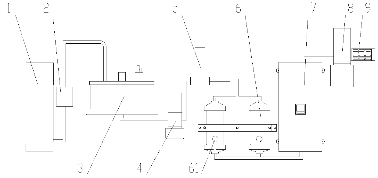
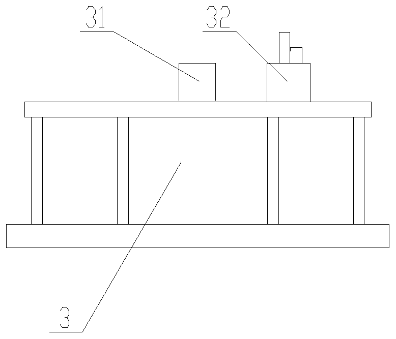
[0020] The overall schematic diagram of an inkjet 3D printer ink degassing system of the present invention is as follows figure 1 shown. Inside the inkjet 3D printer, an ink tank 1, an ink inlet pump 2 and a printing head (not shown in the figure) are arranged. The liquid inlet of ink tank 1 and ink inlet pump 2 is connected with pipeline, and the liquid outlet of ink inlet pump 2 is connected with ink cartridge 3 through pipeline, and the liquid outlet of i...


PUM


Abstract

The invention relates to the field of ink-jet 3D printers, in particular to an ink degassing system of an ink-jet 3D printer. The ink degassing system comprises a printer and degassing films, whereinthe printer comprises an ink tank, an ink inlet pump and a printing head, and the ink tank is connected with a liquid inlet of the ink inlet pump through a pipeline; the ink degassing system is characterized in that a liquid outlet of the ink inlet pump is connected with an ink box through a pipeline, a liquid outlet of the ink box is connected with an electromagnetic pump through a pipeline, an electromagnetic valve is arranged at a liquid outlet of the electromagnetic pump, the electromagnetic valve is connected with the two degassing films through a three-way joint, the two degassing filmsare connected with a negative pressure tank at the same time, the negative pressure tank is connected with a negative pressure pump, and a silencer is arranged at an air outlet of the negative pressure pump; and a control system is arranged in the printer, and the control system is used for controlling the ink inlet pump, the electromagnetic pump and the electromagnetic valve. According to the inkdegassing system of the ink-jet 3D printer, ink can be subjected to degassing treatment, and the phenomena that ink drops are obliquely jetted or are not successfully jetted are avoided, so that theink jetting smoothness of the printing head is ensured, the stability of an ink-jet system is improved, and the rejection rate of equipment is reduced.

Description

technical field [0001] The invention relates to the field of inkjet 3D printers, in particular to an ink degassing system for inkjet 3D printers. Background technique [0002] In the current inkjet 3D printing technology, the ink is sucked into the ink cartridge through the ink inlet pump, and then distributed to each print head by the ink cartridge, and finally the ink is sprayed on the powder surface through the print head. [0003] In the process of transporting the ink from the ink tank to the print head, on the one hand, due to the long transport distance and the shaking during the transport, it is inevitable that the air dissolved in the ink will gather together to generate air bubbles; on the other hand, the printing When the head is working, it continuously sucks and squeezes the internal ink. When sucking, the print head not only sucks the ink from the ink cartridge, but also sucks a small amount of external air. When the air dissolved in the ink is saturated, the f...

Claims


Application Information

Patent Timeline
Patent Type & Authority Applications(China)
IPC IPC(8): B29C64/20B29C64/165B29C64/314B33Y30/00B33Y40/00
CPCB29C64/165B29C64/20B29C64/314B33Y30/00B33Y40/00
Inventor 杨平赵龙闫小龙吴骏志
Owner NINGXIA KOCEL MOLD
Why Eureka
Try Eureka