
Eureka
For R&D, Eureka makes reading and utilizing patents & technical documents easy.
Eureka AIR
Designed for self-driven R&D workflows. Generate viable solutions, solve complex R&D challenges, empower your innovation with AI.

Eureka Materials
Designed for material experts only. Revolutionize your material R&D, from search, analyze, to developing new materials.

TechResearch
Generate reliable direction feasibility study reports for your R&D in just a few steps.

TechSeek
Discover and master advanced knowledge NOW. Basics, ideas, possibilities, all at once.

TechMind
As an expert in R&D Theories, TechMind can generates customized viable solutions instantly.

TechRisk
Analyze your overall solution with one click, know your potential R&D risks in advance.

TechMonitor
Get weekly tech updates, stay abreast of the latest tech innovations and key insights.
Front floor structure, front floor assembly and vehicle
A front floor assembly and front floor technology, which is applied to the superstructure sub-assemblies, vehicle components, vehicle seats, etc., can solve the problem that the front floor assembly is difficult to achieve lightweight and other problems, so as to improve the degree of integration and reduce the weight. , Reduce the effect of welding sequence
- Summary
- Abstract
- Description
- Claims
- Application Information
AI Technical Summary
Problems solved by technology
Method used
Image

Examples
Embodiment 1
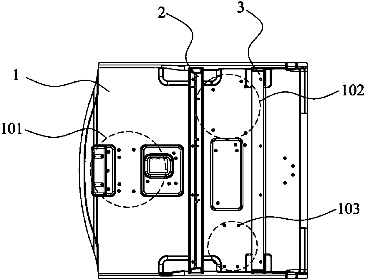
[0055] Such as image 3 As shown, the front floor structure provided by an embodiment of the present invention includes a front floor panel 1, a front seat installation front beam 2 and a front seat installation rear beam 3, the front floor panel 1, the front seat installation front beam 2 The front seat installation rear beam 3 is a composite material, the front seat installation front beam 2 and the front seat installation rear beam 3 are integrally formed on the front floor panel 1, the front seat installation front beam 2 And the front seat installation rear cross beam 3 extends along the width direction of the front floor panel 1 , the front seat installation front cross beam 2 is located in front of the front seat installation rear cross beam 3 .
[0056] In the front floor structure of the embodiment of the present invention, the front floor panel 1, the front seat installation front crossbeam 2 and the front seat installation rear crossbeam 3 are respectively integrall...
Embodiment 2
[0101] Such as Figure 9As shown, the front floor structure provided by another embodiment of the present invention is different from the first embodiment in that the front floor panel 1, the front seat-installed front beam 2 and the front seat-installed rear beam 3 are composite materials, The front seat installation front beam 2 and the front seat installation rear beam 3 are fixedly connected on the front floor panel 1, and the front seat installation front beam 2 and the front seat installation rear beam 3 are installed along the front floor panel. The panel 1 extends in the width direction, and the front seat-mounted front cross member 2 is located in front of the front seat-mounted rear cross member 3 .
[0102] In the front floor structure of the embodiment of the present invention, the front floor panel 1, the front seat-mounted front crossbeam 2 and the front seat-mounted rear crossbeam 3 are composite material parts, and the front seat-mounted front crossbeam 2 and t...
PUM
 Abstract
Description
Claims
Application Information
 - R&D Engineer
- R&D Manager
- IP Professional
- Industry Leading Data Capabilities
- Powerful AI technology
- Patent DNA Extraction
Browse by: Latest US Patents, China's latest patents, Technical Efficacy Thesaurus, Application Domain, Technology Topic, Popular Technical Reports.
© 2024 PatSnap. All rights reserved.Legal|Privacy policy|Modern Slavery Act Transparency Statement|Sitemap|About US| Contact US: help@patsnap.com