Petroleum pipe machining and conveying device

A technology for conveying equipment and oil pipes, which is applied in the direction of conveyors, conveyor objects, transportation and packaging, etc. It can solve the problems of oil pipeline appearance wear and affect the use of pipelines, so as to avoid appearance wear, improve conveying efficiency, and improve conveying order Effect

Inactive Publication Date: 2019-10-11
天长市康弘石油管材有限公司
View PDF7 Cites 5 Cited by
  • Summary
  • Abstract
  • Description
  • Claims
  • Application Information

AI Technical Summary

Problems solved by technology

[0003] The purpose of the present invention is to provide a kind of oil pipe processing and conveying equipment, which solves the problem that the existing oil pipe processing and conveying equipment proposed in the background technology usually uses rollers installed at the bottom of the pipeline to transport the pipeline, which may cause wear on the appearance of the oil pipeline, Issues Affecting the Use of Pipelines

Method used


Image

  • Petroleum pipe machining and conveying device
  • Petroleum pipe machining and conveying device
  • Petroleum pipe machining and conveying device

Examples


Embodiment Construction

[0023] In order to make the technical means, creative features, goals and effects achieved by the present invention easy to understand, the present invention will be further described below in conjunction with specific embodiments.

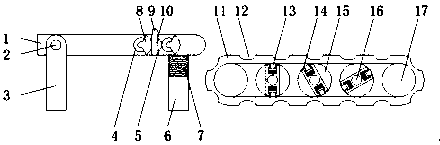
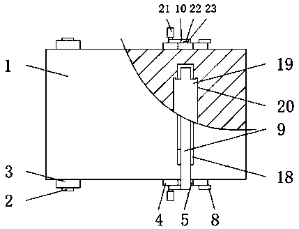
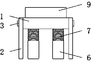
[0024] see Figure 1-5 , the present invention provides a technical solution: a petroleum pipe processing and conveying equipment, including a feed plate 1, a bracket 6 and a conveyor belt 11, the front and rear sides of the feed plate 1 are equipped with a fixed frame 3 through a rotating shaft 2, so The bottom of the feed plate 1 is provided with a support 6, the top of the support 6 is equipped with a first spring 7, the top of the first spring 7 is fixedly connected with the bottom of the feed plate 1, and the top of the feed plate 1 The front and rear side walls are all equipped with a second gear 5, and the left and right sides of the second gear 5 are equipped with a first gear 4 meshing with the second gear 5, and the first gear 4 is away ...


PUM


Abstract

The invention discloses a petroleum pipe machining and conveying device which comprises a feeding plate, a support and a conveyor belt. The front and back sides of the feeding plate are provided withfixing frames through rotating shafts, the support is arranged at the bottom of the feeding plate, a first spring is installed at the top of the support, the top of the first spring is fixedly connected with the bottom of the feeding plate, the front and back side walls of the feeding plate are each provided with a second gear, the left and right sides of the second gears are each provided with afirst gear meshed with the second gears, and a third gear is installed at the side, away from the feeding plate, of each first gear. Due to a placement groove in the outer side wall of the conveyor belt, a pipeline to be transported is supported, surface contact between a pipeline and a placement component is achieved, the phenomenon that use of the pipeline is affected due to the fact that the appearance is abraded by the excessively small contact part is avoided, meanwhile, the pipe can be stable due to the placement groove, the phenomenon that the pipe rolls and transportation is hindered is avoided, and the device is suitable for being widely used and popularized.

Description

technical field [0001] The invention relates to the field of pipelines, in particular to a processing and conveying equipment for petroleum pipes. Background technique [0002] A pipeline is a device connected by pipes, pipe connectors and valves to transport gas, liquid or fluid with solid particles. It is mainly used for water supply, drainage, heat supply, gas supply, long-distance transportation of oil and natural gas, agricultural Among irrigation, hydraulic engineering and various industrial installations, oil pipelines are one of them. Before the oil pipelines are used, they are processed. During the processing, conveying equipment will be used. The existing oil pipe processing and conveying equipment are generally used to install The rollers at the bottom of the pipeline may cause wear to the appearance of the oil pipeline and affect the use of the pipeline. Therefore, we propose an oil pipe processing and conveying equipment. Contents of the invention [0003] T...

Claims


Application Information

Patent Timeline
Patent Type & Authority Applications(China)
IPC IPC(8): B65G15/58B65G47/04B65G47/24
CPCB65G15/58B65G47/04B65G47/24B65G2201/0217
Inventor 吕黎红陶东陈留军
Owner 天长市康弘石油管材有限公司
Why Eureka
Try Eureka