Blower capable of conducting self-physical cooling

A physical cooling and blower technology, which is applied in mechanical equipment, machines/engines, liquid fuel engines, etc., can solve the problems of reduced service life of blowers, increased maintenance costs and replacement costs, and increased use time of blowers to reduce friction and noise Effect

Active Publication Date: 2019-10-11
ANHUI RUIBANG BIOLOGICAL SCI & TECH CO LTD
View PDF10 Cites 2 Cited by
  • Summary
  • Abstract
  • Description
  • Claims
  • Application Information

AI Technical Summary

Problems solved by technology

[0006] The purpose of the present invention is to provide a kind of air blower that can self-physically cool down, to solve the above-mentioned and existing blower structures proposed in the above-mentioned background technology. Due to the high temperature of the blower itself during use, the service life is reduced, which further increases the maintenance cost and replacement cost; the design in this patent can perform its own physical cooling through the operation of the blower itself, and the design of this patent is carried out by double means. Heat dissipation from the inside out, so as to fully dissipate heat from the blower, thereby effectively increasing the use time of the blower

Method used


Image

  • Blower capable of conducting self-physical cooling
  • Blower capable of conducting self-physical cooling
  • Blower capable of conducting self-physical cooling

Examples


Embodiment

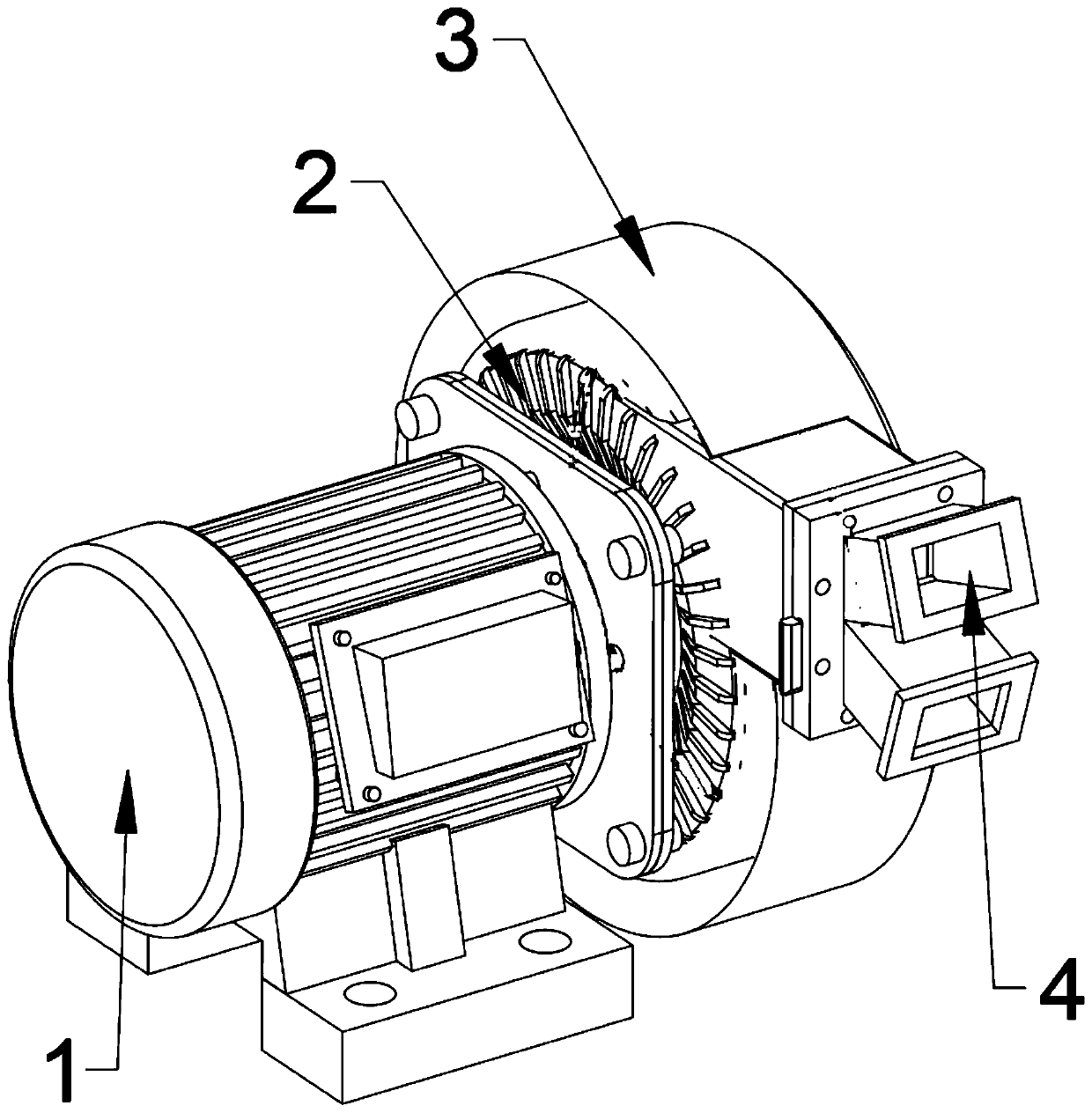
[0036] as attached figure 1 to attach Figure 8 Shown:

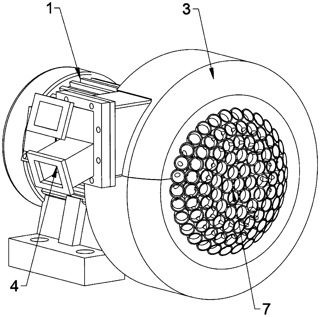
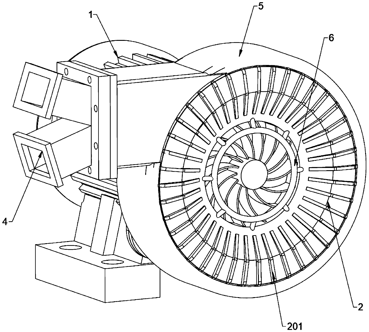
[0037] The present invention provides a blower capable of self-physical cooling, including: a motor 1, a blower device 2, a heat sink 201, a drainage cover 3, a flow guide duct 4, a flow guide plate 401, a cooling device 5, a fixing frame 6, Air cooling device 7 and tapered groove 701; one side of the motor 1 is fixed with a blower device 2, and the motor 1 is connected to the blower device 2 in transmission; the outer wall of the blower device 2 is provided with cooling fins 201 ; the outer side of the cooling fin 201 is provided with a cooling device 5 ; the air cooling device 7 is installed on the tapered inner wall of the drainage cover 3 .

[0038] Wherein, the inner side of the cooling device 5 is a hollow device, and the inner side of the cooling device 5 is filled with a heat-conducting cooling liquid. image 3 shown.

[0039] Wherein, the outer wall of the blower device 2 is provided with a plurality of cool...


PUM


Abstract

The invention provides a blower capable of conducting self-physical cooling. The blower comprises a motor, a blowing device, cooling fins, a drainage cover, a flow guide air flue, a flow guide plate,a cooling device, a fixing frame, an air cooling device and a conical groove, wherein the blowing device is fixed on one side of the motor through bolts, the motor is connected with the blowing devicein a transmission mode, and the cooling fins are arranged on the outer wall of the blowing device; and the cooling device is arranged on the outer sides of the cooling fins, and the air cooling device is installed on the conical inner wall of the drainage cover. The blower capable of conducting the self-physical cooling covers the outer wall of the blowing device in an annular structure, an innerring of the drainage cover is fixed on the fixing frame at the air inlet of the blowing device, the design of the drainage cover is beneficial to drainage of part of air so that the air quickly passes through the surface of the cooling device, then the cooling device can quickly dissipate heat, and the air blowing device can be better cooled.

Description

technical field [0001] The invention relates to the technical field of blower equipment, in particular to a blower capable of self-physical cooling. Background technique [0002] The blower is mainly composed of the following six parts: motor, air filter, blower body, air chamber, base (and fuel tank), and drip nozzle. The blower operates eccentrically by the biased rotor in the cylinder, and makes the volume change between the vanes in the rotor slot suck, compress and spit out air. During operation, the pressure difference of the blower is used to automatically send lubrication to the drip nozzle, and drip into the cylinder to reduce friction and noise, and at the same time keep the gas in the cylinder from flowing back. This type of blower is also called a sliding vane blower. [0003] After patent retrieval, the existing patent number is 201610654858.9, which is an invention of a blower, including a motor, a blower body, an air chamber and a base. A wind pressure sensor...

Claims


Application Information

Patent Timeline
Patent Type & Authority Applications(China)
IPC IPC(8): F04D29/58F04D29/42F04D29/44F04D29/46F04D25/08
CPCF04D25/08F04D29/4213F04D29/441F04D29/462F04D29/582F04D29/5853
Inventor 蔡祈坤
Owner ANHUI RUIBANG BIOLOGICAL SCI & TECH CO LTD
Why Eureka
Try Eureka