
Tensile test device and heating device

A technology for tensile testing and heating devices, applied to measuring devices, using stable tension/pressure to test material strength, instruments, etc., can solve problems such as temperature loss

Active Publication Date: 2019-10-11
HENAN INST OF ENG +1
View PDF10 Cites 3 Cited by
  • Summary
  • Abstract
  • Description
  • Claims
  • Application Information

AI Technical Summary

Problems solved by technology

[0004] The purpose of the present invention is to provide a heating device to solve the problem of temperature loss caused by the need to separate from the heating device during the tensile test of the tensile test piece in the prior art, and can simultaneously heat more than two tensile test pieces; the present invention The purpose is also to provide a tensile test device using the heating device

Method used


Image

  • Tensile test device and heating device
  • Tensile test device and heating device
  • Tensile test device and heating device

Examples


Embodiment Construction

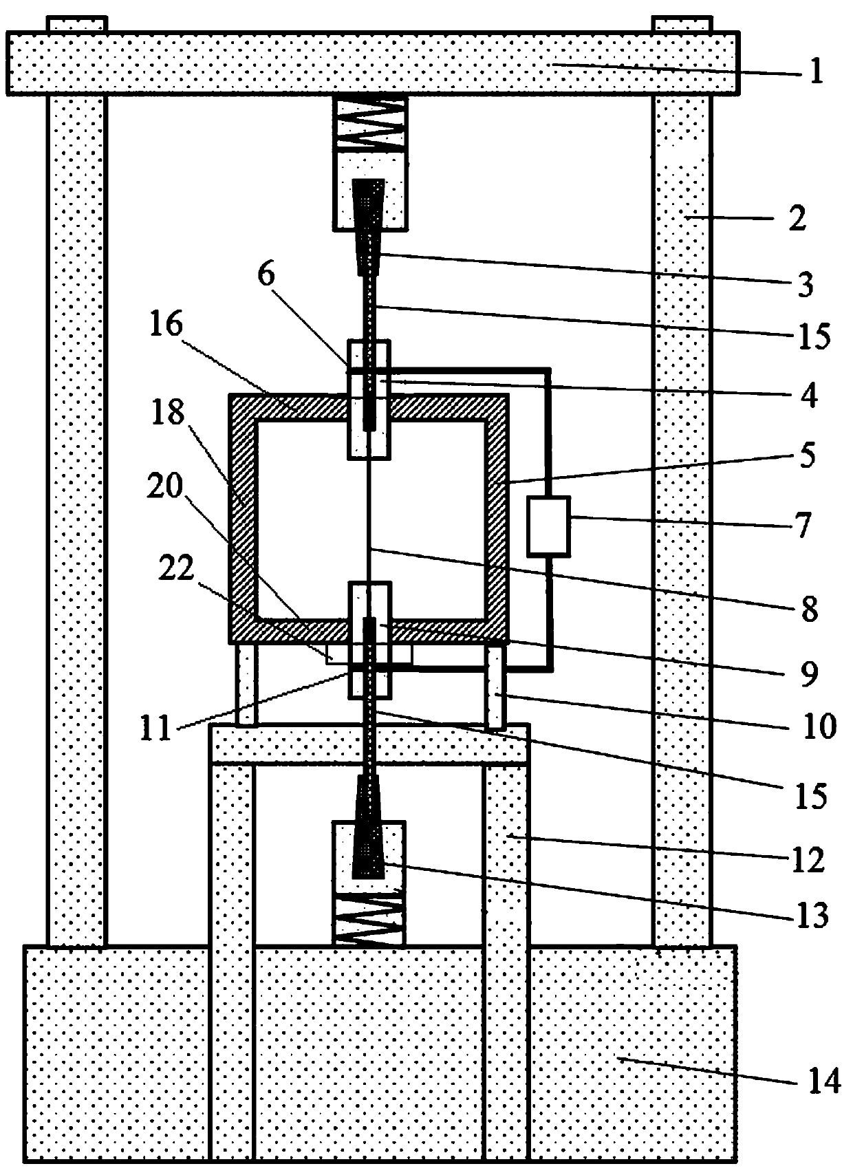
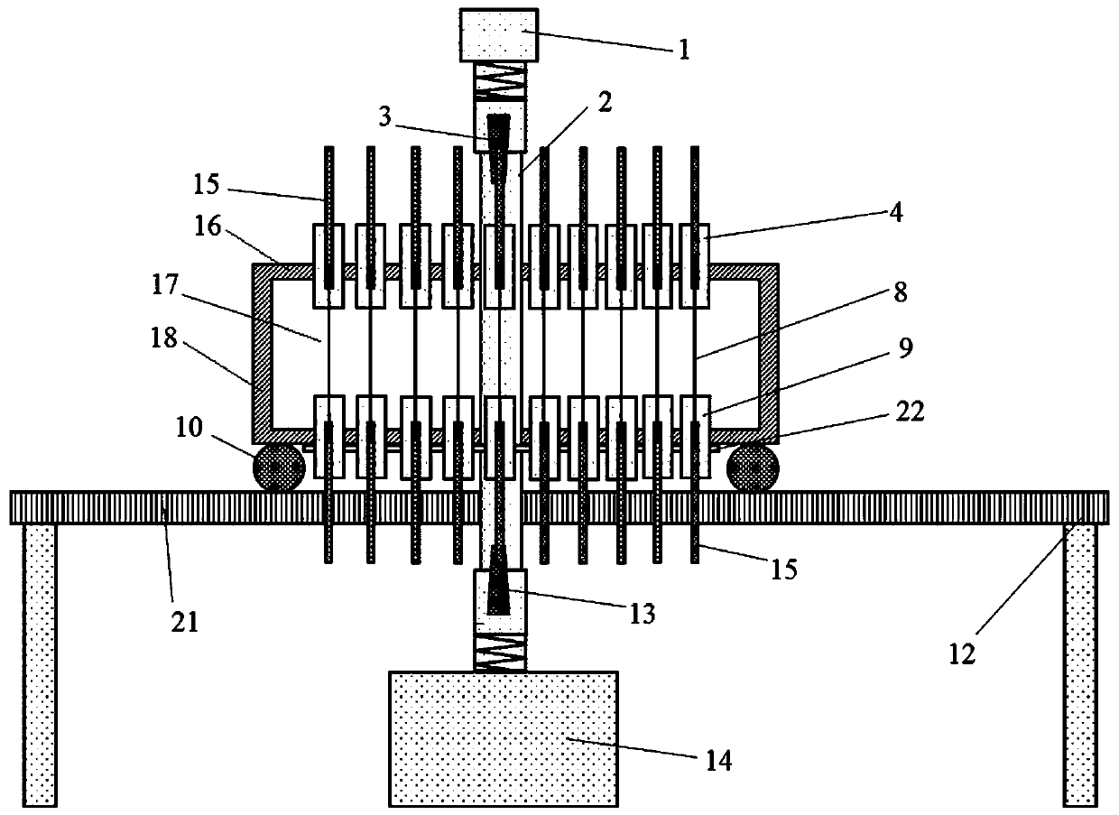
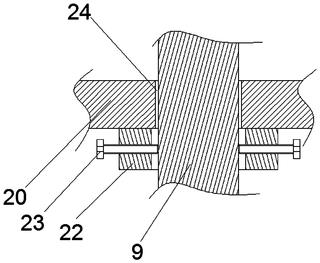
[0018] An example of a tensile test apparatus such as Figure 1~3 Shown: including heating device, tensile testing machine, tensile test piece 17 and large deformation extensometer 7. The tensile testing machine is a conventional tensile testing machine for steel bars, which includes a base 14, on which four columns 2 are arranged, and a beam 1 that can move up and down is equipped with a guiding movement on the column 2. The loading head connected with the reinforcing bar, in the present embodiment, the loading head on the beam is called the upper loading head 3, and the loading head on the base is called the lower loading head 13, wherein the lower loading head is driven by the loading mechanism, in the present embodiment The loading mechanism is a vertically arranged loading cylinder. The upper loading head and the lower loading head belong to the prior art, and will not be described in detail here.

[0019] The heating device includes a heating furnace support 12 and a he...


PUM


Abstract

The invention relates to a tensile test device and a heating device, and the tensile test device comprises the heating device and a tensile test machine, wherein the tensile test machine comprises loading heads capable of moving oppositely and reversely, the heating device comprises a heating furnace bracket and a heating furnace guiding and moving front and rear and assembled on the heating furnace bracket, the heating furnace is provided with at least two test piece perforations perforating through the upper furnace wall and the lower furnace wall of the heating furnace in the up-and-down direction, the respective test piece perforations are arranged at intervals in the front-rear direction, and the heating furnace is provided with a fixing device corresponding to the test piece perforations for detachably fixing the tensile test pieces in the test piece perforations. The invention solves the problem in the prior art that the tensile test pieces need to be separated from the heatingdevice to cause temperature loss during the tensile test, and can simultaneously heat two or more tensile test pieces.

Description

technical field [0001] The invention relates to a tensile test device for performing a tensile test on a tensile test piece in a high-temperature environment. Background technique [0002] In recent years, with the development trend of high-rise, long-span, lightweight and durability in the field of civil engineering, steel fiber-containing concrete materials such as steel fiber concrete and ultra-high performance concrete have been used in high-rise buildings, complex structures, and large buildings. Span bridges, special conditions of use and harsh environments (such as offshore platforms, subsea tunnels, nuclear facilities and military protection projects) are more and more widely used in fields such as steel fiber concrete, ultra-high performance concrete and other materials. New requirements have been put forward, and the research on its fire resistance has also become a hot spot. [0003] The degradation of mechanical properties of steel fiber reinforced concrete and ...

Claims


Application Information

Patent Timeline
Patent Type & Authority Applications(China)
IPC IPC(8): G01N3/18G01N3/02
CPCG01N3/18G01N3/02G01N2203/0226G01N2203/0682G01N2203/0017
Inventor 赵亮平陈刚袁健松高丹盈秦道天法冠喆王聪王宜双李小伟马娟杨建强刘红丽
Owner HENAN INST OF ENG
Learn More