Intelligent lock test device

A technology for testing equipment and smart locks, applied in the testing of mechanical components, testing of machine/structural components, measuring devices, etc.

Pending Publication Date: 2019-10-11
东莞颀达联合实业有限公司
View PDF0 Cites 3 Cited by
  • Summary
  • Abstract
  • Description
  • Claims
  • Application Information

AI Technical Summary

Problems solved by technology

In the existing smart lock testing process, the staff usually use corresponding tools to manually test the smart lock, so as to obtain test results such as life test and stability test. However, this test method only tests the smart lock under the same environmental conditions. The lock performs unlocking, opening, closing, and locking actions and records the number of operations and the problems reflected during the test. When the smart locks that pass the test are used in the corridor, they are consistent with the test results. If the smart lock is in contact with the outdoor environment When in use, it is often affected by rain, temperature, humidity and other conditions and the test results are inconsistent. It can be seen that there is a lack of a smart lock life testing device that can test the service life in various actual environments in the prior art.

Method used


Image

  • Intelligent lock test device
  • Intelligent lock test device
  • Intelligent lock test device

Examples


Embodiment Construction

[0027] In order to further understand the structure, features and other purposes of the present invention, the attached preferred embodiments are now described in detail with accompanying drawings as follows. The embodiments described in the accompanying drawings are only used to illustrate the technical solutions of the present invention and are not limiting this invention.

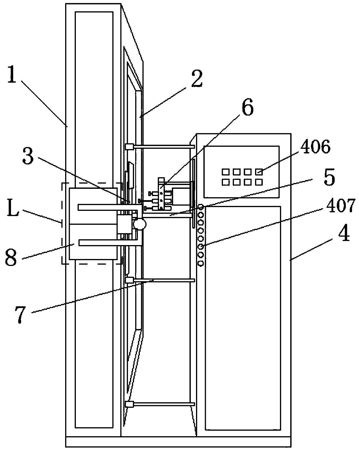
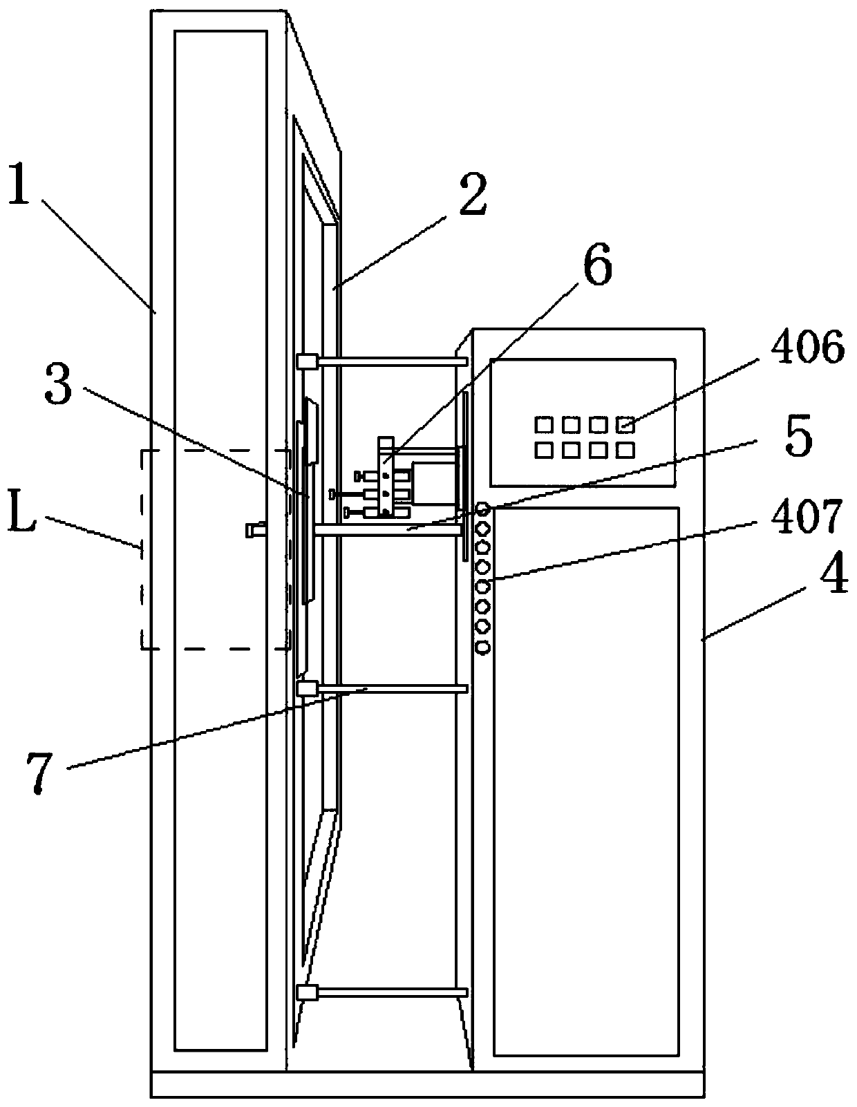
[0028] Such as figure 1 and Figure 10 as shown, figure 1 It is a schematic structural diagram of the smart lock testing device of the present invention, Figure 10 It is the electrical control schematic diagram of the intelligent lock testing equipment of the present invention; the intelligent lock testing equipment includes a fixed frame 1, a door frame 2 installed on the fixed frame 1, an intelligent lock 3 fixed on the door frame 2, and an intelligent lock 3 erected on the The control box 4 on one side is equipped with a handle testing mechanism 5, an analog pressing password mechanism 6 and an an...


PUM


Abstract

The invention provides an intelligent lock test device. The device includes a low temperature test box and a high temperature test box arranged in parallel. An electric heating tube is arranged in thehigh temperature test box in a suspension and hanging manner. Two ends of the electric heating tube are electrically connected to a power source in a control box through a connecting wire. Hot air tubes facing the electric heating tube are arranged on the front and the back of the high temperature test box in an insertion manner. A dry ice box is provided on the top in the low temperature test box. Cold air tubes communicating the dry ice box are arranged on the front and the back of the low temperature test box in an insertion manner. Air inlet ends of the hot air tubes and the cold air tubes communicate a blower by a reversing valve. The blower is electrically connected to the power source in the control box. The reversing valve is electrically connected with a programmable logic controller (PLC) in the control box. Multiple air outlets are arranged on the air outlet ends of the hot air tubes and the cold air tubes in a manner of facing the intelligent lock. The temperature of the environment around the intelligent lock test device is increased or decreased so as to test responses in the process of unlocking, door opening, door closing and locking in an high or low temperature environment.

Description

technical field [0001] The invention relates to the technical field of intelligent lock testing, in particular to an intelligent lock testing equipment. Background technique [0002] Since smart locks are security and security facilities, they need to undergo strict monitoring and testing before leaving the factory to ensure that each batch of smart locks can be put into use stably and reliably. In the existing smart lock testing process, the staff usually use corresponding tools to manually test the smart lock, so as to obtain test results such as life test and stability test. However, this test method only tests the smart lock under the same environmental conditions. The lock performs unlocking, opening, closing, and locking actions and records the number of operations and the problems reflected during the test. When the smart locks that pass the test are used in the corridor, they are consistent with the test results. If the smart lock is in contact with the outdoor envir...

Claims


Application Information

Patent Timeline
Patent Type & Authority Applications(China)
IPC IPC(8): G01N17/00G01M13/00
CPCG01M13/00G01N17/00G01N17/002
Inventor 周永强
Owner 东莞颀达联合实业有限公司
Why Eureka
Try Eureka