Lidar system

A lidar and laser technology, applied in radio wave measurement systems, optics, optical components, etc., can solve problems such as vertical scanning distortion, and achieve the effect of small motion rotation quality

Pending Publication Date: 2019-10-11
ROBERT BOSCH GMBH
View PDF2 Cites 0 Cited by
  • Summary
  • Abstract
  • Description
  • Claims
  • Application Information

AI Technical Summary

Problems solved by technology

This has the disadvantage that at least one power supply and at least one data transmission must be implemented on the rotating element
[0007] Another disadvantage of some lidar systems known from the prior art is that the vertical scan is rotationally distorted when the laser is tilted out of a horizontal plane

Method used


Image

  • Lidar system
  • Lidar system
  • Lidar system

Examples


Embodiment Construction

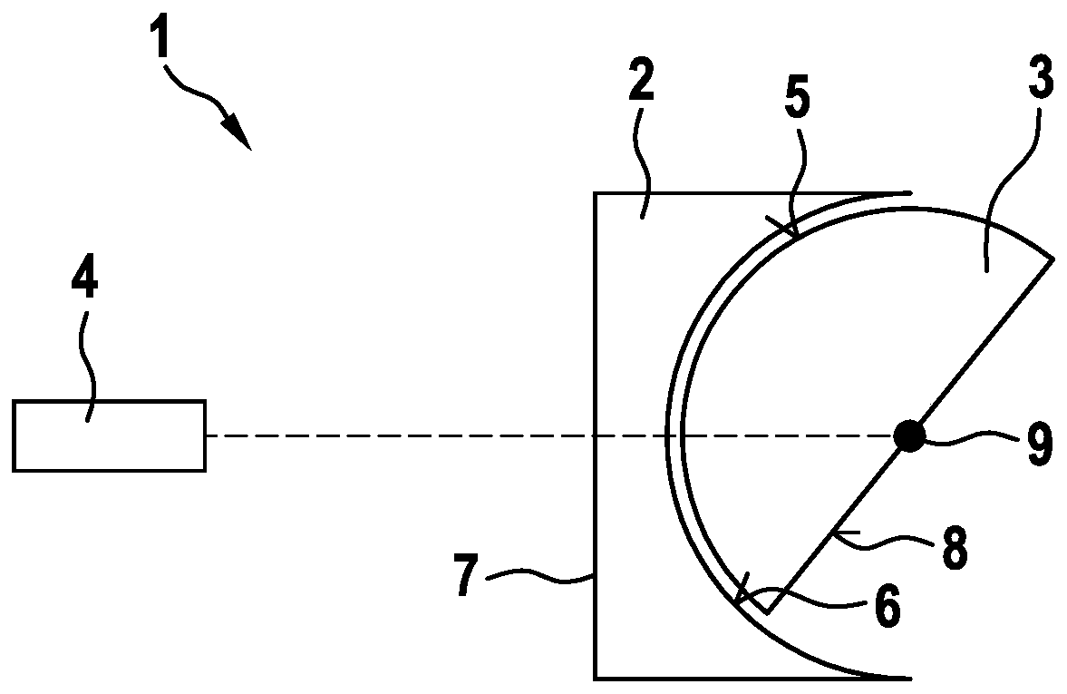
[0031] exist figure 1 The lidar system 1 according to the first embodiment is shown in a schematic top view in . The lidar system 1 includes optics. The optics has a first lens 2 . The first lens 2 is arranged statically in this exemplary embodiment. The optics has a second lens 3 . In this exemplary embodiment, the second lens 3 is mounted so that it can rotate in relation to the first lens 2 . The first lens 2 and the second lens 3 are located on a common optical path. This beam path is the path followed by the light beam emitted by the light source 4 (here a laser) of the LiDAR system 1 . exist figure 1 In and in all following figures, the dotted line indicates the radiation direction of the light beam from the light source 4 . The radiation direction is also referred to here as the main radiation direction. The light source 4 is arranged statically with respect to the first lens 2 . The invention therefore relates to the optimization of the lidar system 1 accordin...


PUM


Abstract

The invention provides a LiDAR system (1) which includes an optical system that encompasses a first lens (2), which is preferably statically positioned, and a second lens (3), which is preferably rotatably supported in relation to the first lens (2). The first lens (2) and the second lens (3) are situated along a shared optical path, and at least either the first lens (2) or the second lens (3) isconfigured to be set into rotation in order to bring about a beam deflection from the optical path in at least one spatial direction.

Description

technical field [0001] The invention relates to a lidar system comprising an optical arrangement comprising a first lens, preferably statically arranged, and a second lens, preferably statically arranged with respect to the first lens. Mounted in a rotationally movable manner, the first lens and the second lens being located on a common beam path. Background technique [0002] The acronym LiDAR stands for Light detection and ranging. Like radar sensors, lidar methods are based on sending electromagnetic beams into the surrounding environment. A LiDAR sensor can be implemented as a scanner and can perform distance measurements on objects in the surrounding environment. LiDAR is increasingly used in motor vehicles in order, for example, to monitor traffic in the surrounding environment. For example, the distance to an object (for example a car) in the surroundings and the speed of this object can be determined with the aid of lidar. LiDAR systems generally include at least...

Claims


Application Information

Patent Timeline
Patent Type & Authority Applications(China)
IPC IPC(8): G01S7/481G01S17/931
CPCG01S7/481G01S7/4817G02B26/0875G01S17/42G01S17/06G02B26/10G01S17/931
Inventor M·拜尔
Owner ROBERT BOSCH GMBH
Why Eureka
Try Eureka