
Metal reflector support structure and metal reflector system

A metal mirror and support structure technology, applied in the directions of instruments, installation, optics, etc., can solve the problems of astigmatism of the mirror, unable to meet the optical index, the mirror cannot be supported by peripherals, etc., to achieve the effect of compressing the size and compact layout

Active Publication Date: 2020-09-01
CHANGCHUN INST OF OPTICS FINE MECHANICS & PHYSICS CHINESE ACAD OF SCI
View PDF7 Cites 0 Cited by
  • Summary
  • Abstract
  • Description
  • Claims
  • Application Information

AI Technical Summary

Problems solved by technology

[0004] In the field of space mirror support, the existing patent title is "Adjustable Mirror Bipod Flexible Support Structure and Support Device", the patent application number is 201720931601.3, which adopts the peripheral support method of the mirror Bipod flexible structure, and the typical mirror in this invention The material is silicon carbide, which can meet the support requirements of space mirrors, but it cannot be directly applied to the support of metal mirrors
At the same time, when there are space constraints, the mirror cannot be supported by the periphery and needs to be supported by the back. For the flexible support structure scheme of Bipod on the back, the mirror will produce astigmatism, which cannot meet the optical specifications

Method used


Image

  • Metal reflector support structure and metal reflector system
  • Metal reflector support structure and metal reflector system
  • Metal reflector support structure and metal reflector system

Examples


Embodiment Construction

[0031] The following will clearly and completely describe the technical solutions in the embodiments of the present invention with reference to the accompanying drawings in the embodiments of the present invention. Obviously, the described embodiments are only some, not all, embodiments of the present invention. Based on the embodiments of the present invention, all other embodiments obtained by persons of ordinary skill in the art without making creative efforts belong to the protection scope of the present invention.

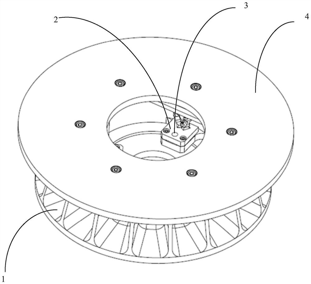
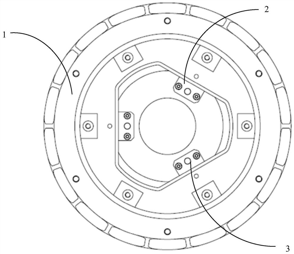
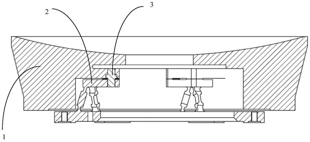
[0032] see Figure 1 to Figure 3 , is a structural schematic diagram of a metal mirror support structure provided in Embodiment 1 of the present invention, including: a base 4 and a mirror back plate 2, the mirror back plate 2 is fixedly connected to the base 4, and the optical reflection The mirror 1 is fixedly connected to the reflector back plate 2, the reflector back plate 2 includes a flexible support, and the optical reflector 1 is installed on the plane...


PUM


Abstract

The metal reflector support structure provided by the present invention includes: a base and a reflector back plate, the reflector back plate is fixedly connected to the base, an optical reflector is fixedly connected to the reflector back plate, and the reflector The mirror back plate includes a flexible support, and the optical mirror is installed on the plane where the flexible support is located. When the mirror has an assembly error, the flexible support can compensate through its own elastic deformation. In the supporting structure of the metal mirror provided by the invention, when the optical mirror is subjected to gravity, temperature changes or assembly errors, the flexible support member compensates through its own elastic deformation, so as to avoid affecting the surface shape accuracy of the mirror. In addition, the present invention also provides a metal reflector system comprising the support structure of the metal reflector.

Description

technical field [0001] The invention relates to the technical field of optical processing, in particular to a supporting structure of a metal reflector. Background technique [0002] Catadioptric optical systems are widely used in the fields of optical measurement and remote sensing. With the rapid development of science and technology, the catadioptric optical system of photoelectric remote sensing equipment is developing in the direction of dexterity, light weight and high resolution, and higher requirements are put forward for the volume and weight of the catadioptric optical system. Due to the advantages of short processing cycle, good processing technology and low material price, metal mirrors are gradually applied in catadioptric optical systems. [0003] The metal mirror is the core component of the catadioptric optical system. In order to meet the high-resolution requirements of the detector, it must have high-quality optical surface accuracy. For this reason, it i...

Claims


Application Information

Patent Timeline
Patent Type & Authority Patents(China)
IPC IPC(8): G02B7/185G02B7/198
CPCG02B7/182
Inventor 谭淞年许永森周平伟石磊
Owner CHANGCHUN INST OF OPTICS FINE MECHANICS & PHYSICS CHINESE ACAD OF SCI
Learn More