Mold production method, and molded article production method using same

A manufacturing method and technology of a molded body, which are applied to the manufacture of molds and the manufacturing field of molded bodies using the manufacture, can solve the problems of large curing shrinkage rate and the like, and achieve the effect of excellent surface accuracy

Inactive Publication Date: 2020-10-02
DAICEL CHEM IND LTD +2
View PDF6 Cites 0 Cited by
  • Summary
  • Abstract
  • Description
  • Claims
  • Application Information

AI Technical Summary

Problems solved by technology

However, its curing shrinkage rate is large, and there is a problem when a high-precision three-dimensional transfer shape is desired
In addition, in order to suppress the cure shrinkage of the ultraviolet curable composition, various studies have been conducted on the composition, but there are still limitations.

Method used


Image

  • Mold production method, and molded article production method using same
  • Mold production method, and molded article production method using same
  • Mold production method, and molded article production method using same

Examples


experiment example 1

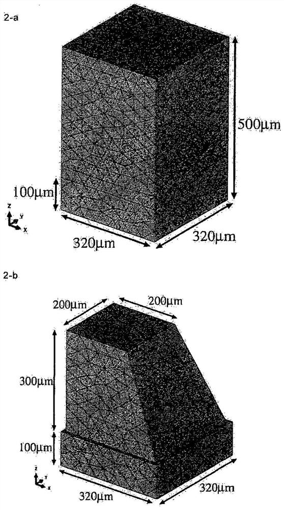
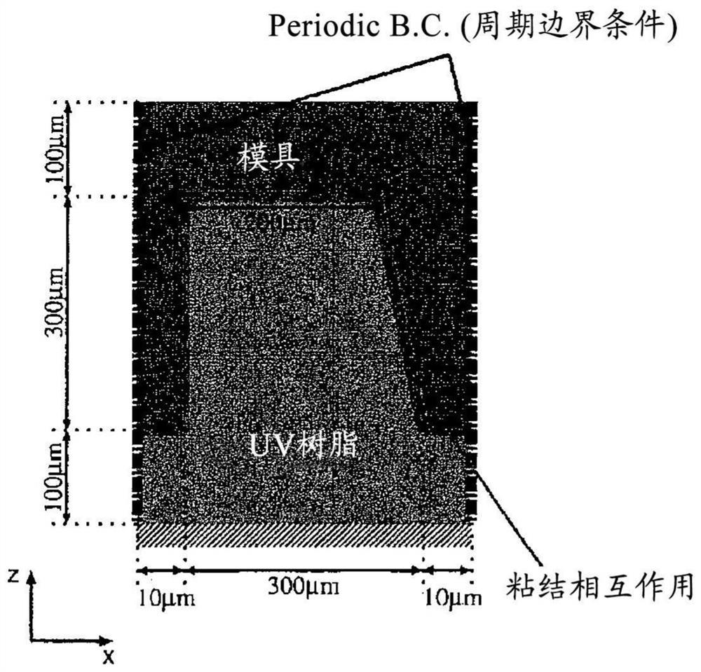
[0144] Coat the mold with an ultraviolet curable composition (trade name "CELVENUS OUH106", containing a cationic curable compound and a photocationic polymerization initiator, and 80% by weight of the total amount of the cationic curable compound is an epoxy resin (containing a multifunctional alicyclic Formula epoxy compound) manufactured by Daicel Co., Ltd., closed the mold from above with a transparent substrate. Then, UV irradiation (80mW × 30 seconds) was carried out, and then, mold release was carried out to obtain a molded body ( Figure 6 ). In the obtained molded body, bending displacement occurred from the central part of the side surface to the lower central part.

Embodiment 1

[0145] Example 1 (Study on Bending from the Center to the Lower Center of the Side of the Molded Body)

[0146] Modeling was performed by replacing curing shrinkage caused by irradiating the ultraviolet curable composition with ultraviolet rays to shrinkage and solidification caused by cooling the thermoviscoelastic body.

[0147]

[0148] Thermal linear expansion coefficient: 0.0001K -1

[0149] Instant Young's modulus: 250MPa

[0150] Instant Poisson's Ratio: 0.3

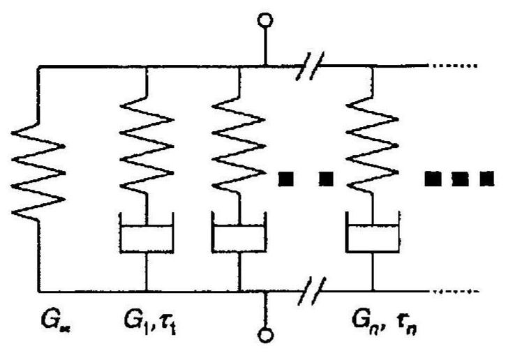
[0151] Generalized Maxwell model:

[0152] g 1 =0.99999

[0153] τ 1 =1.0sec.

[0154] Time-temperature conversion rule (WLF equation):

[0155] θ 0 : 25°C

[0156] C 1 =10

[0157] C 2 : 100°C

[0158] Additionally, the mold was modeled based on Neo-Hooke elastomers.

[0159]

[0160] Initial Young's modulus: 5MPa

[0161] Initial Poisson's ratio: 0.49

[0162] The finite element analysis using the tetrahedral quadratic modified hybrid element (C3D10MH) of ABAQUOS / Standard was carried out acc...

Embodiment 2

[0177] The finite element analysis was performed under the same conditions as in Example 1 except that the initial Young's modulus of the mold was changed to 1000 GPa. As a result, the sectional view perpendicular to the y-axis at the time t=100s of Step2 ( Figure 10 ), no bending at the central portion of the side of the molded body was observed.

[0178] From this, it can be confirmed that the tube formation due to the flexibility of the mold is involved in the display of the curvature of the central portion of the side surface of the molded body.

[0179] From the results of Examples 1 and 2, and Experimental Example 1, it was confirmed that the cure shrinkage of the resin and the deformation of the mold accompanying the cure shrinkage were involved in the development of the curve from the center to the lower center of the side of the molded body. In addition, it was confirmed that the deformation of the molded body can be accurately simulated when the calculation is perf...


PUM

PropertyMeasurementUnit
heightaaaaaaaaaa
thicknessaaaaaaaaaa
thicknessaaaaaaaaaa

Abstract

Provided is a mold production method whereby it is possible to mold a UV-curable composition with excellent accuracy by means of photoimprinting. This mold production method is a production method fora mold comprising an elastic body and used in molding a UV-curable composition, and is characterized in that deformation accompanying curing of the UV-curable composition is simulated using finite element analysis taking into consideration curing shrinkage [1] of the UV-curable composition and deformation [2] of the mold accompanying the shrinkage, and the mold is designed on the basis of the simulation results.

Description

technical field [0001] The present invention relates to a method for producing a mold made of an elastomer used for molding an ultraviolet curable composition, and a method for producing a molded body using the mold produced by the method. This application claims the priority of Japanese Patent Application No. 2018-27432 filed in Japan on February 19, 2018, and Japanese Patent Application No. 2018-174162 filed in Japan on September 18, 2018, and their contents are cited in this. Background technique [0002] Imprinting (imprint) is a microfabrication technique capable of transferring a nano-sized pattern using a very simple process. Since mass production can be realized at low cost by imprinting, it has been put into practical use in various fields such as semiconductor devices and optical components. [0003] For example, the micromirror array is an optical component formed by arranging a plurality of square prisms and square pyramids with a side length of 100 to 1000 μm ...

Claims


Application Information

Patent Timeline
Patent Type & Authority Applications(China)
IPC IPC(8): B29C33/42B29C59/02
CPCB29D11/00596B29C33/3842B29C2035/0827B29C37/005G03F7/0002B29C33/405B29C33/42B29C59/02B29C33/3835B29C35/0805B29K2063/00B29K2995/0012
Inventor 石川慎介藤川武大西有希平井义彦
Owner DAICEL CHEM IND LTD
Why Eureka
Try Eureka