Method for calculating for products of coal liquefaction reaction

A liquefaction product, coal liquefaction technology, applied in the preparation of liquid hydrocarbon mixtures, petroleum industry, etc., can solve the problems of large research costs and time, and achieve the effect of saving money and time, and optimizing the shape

Inactive Publication Date: 2001-07-04
CHIYODA CORP
View PDF0 Cites 0 Cited by
  • Summary
  • Abstract
  • Description
  • Claims
  • Application Information

AI Technical Summary

Problems solved by technology

Subsequent research costs and time are required for each coal type

Method used


Image

  • Method for calculating for products of coal liquefaction reaction
  • Method for calculating for products of coal liquefaction reaction
  • Method for calculating for products of coal liquefaction reaction

Examples


Embodiment 1

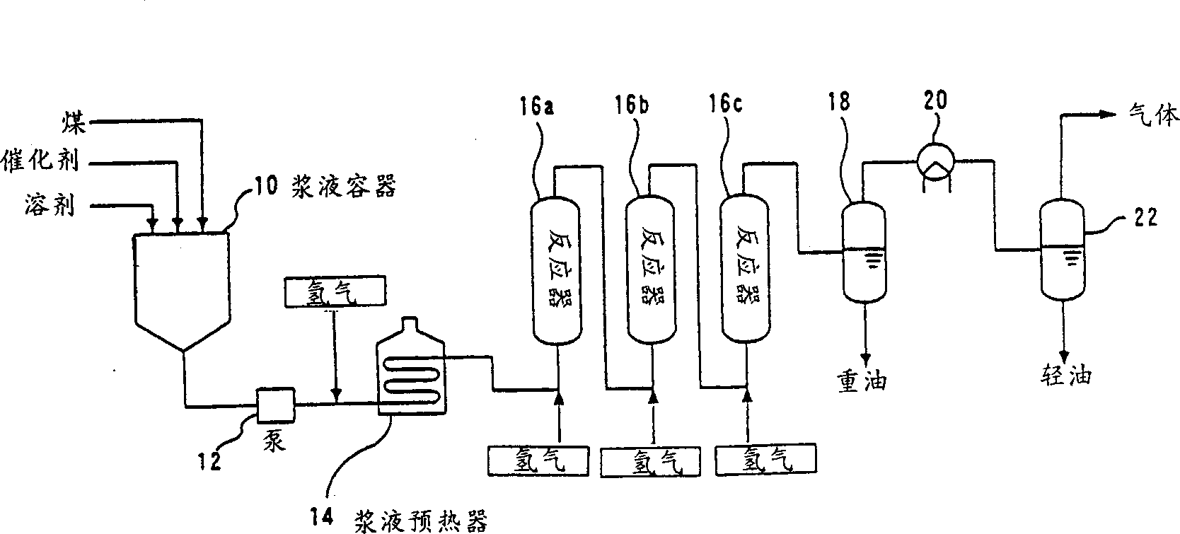
[0187] The method of estimating the flow rate at the outlet of a coal liquefaction reactor consisting of three sequentially connected bubble columns is now exemplified by the program of the present invention. The kij values ​​of raw coal A and [C A ], [C B ] and [C I ] values ​​are obtained through experiments. Tables 3 and 4 show the dimensions of the bubble column, the reaction temperature, the reaction pressure and the flow rate mi,0 of each component at the inlet of the first column.

[0188] first tower

second tower

third tower

Inner diameter of reactor cm

The effective length of the reactor cm

The internal volume of the reactor L

Gas space velocity cm / s

Slurry space velocity cm / s

Gas retention value-

Slurry residence time sec

Reactor temperature °C

Reactor pressure kg / cm 2

Injected hydrogen gas kg / h

100.0

1100.0

8640.0

5.9

0.20

0.387

3442

476

171

...

Embodiment 2

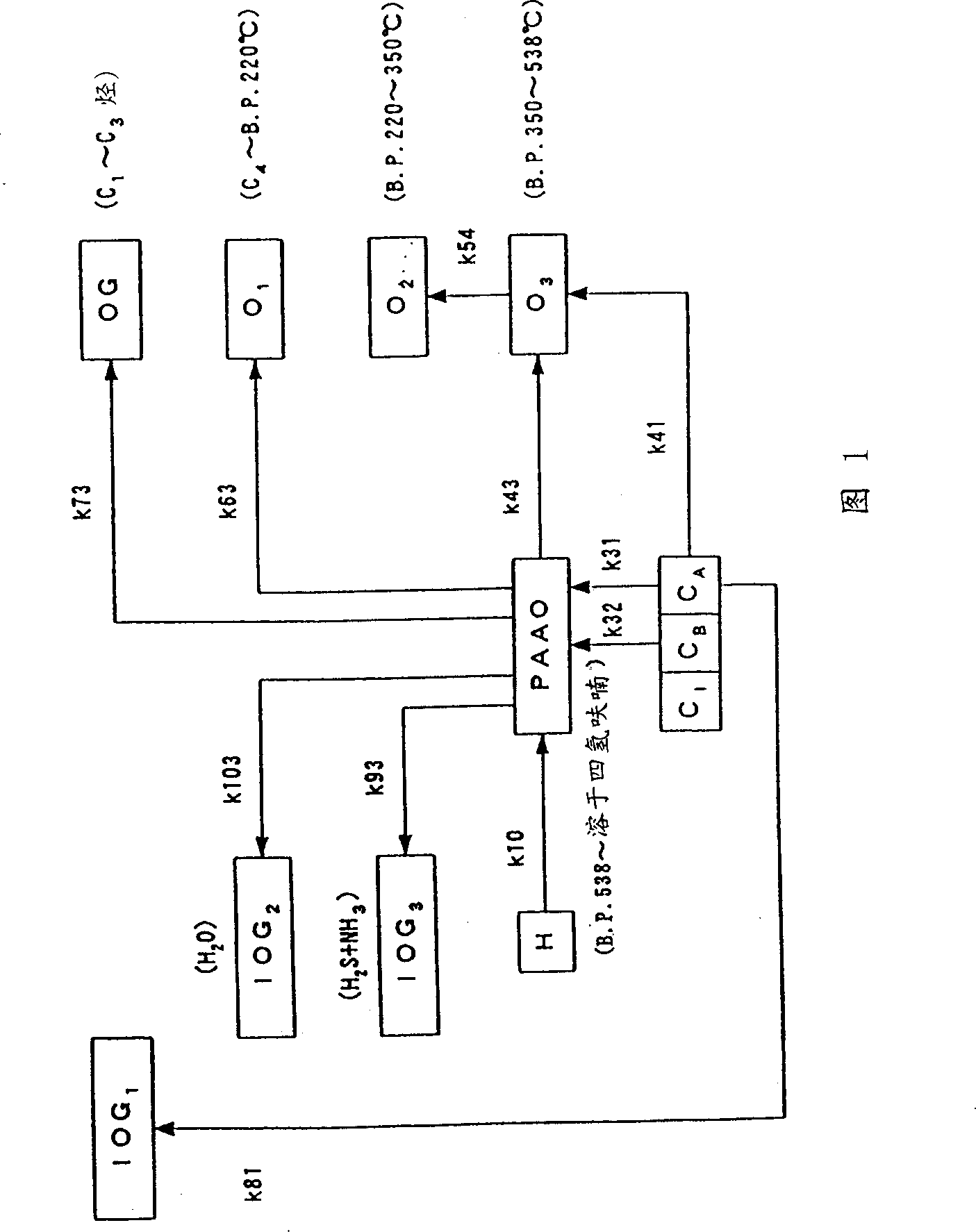
[0199] The procedure of the present invention is used to calculate reaction rate constants based on actual measurements of the flow velocity at the outlet of a coal liquefaction reactor consisting of three sequentially connected bubble columns. The raw coal [C A ], [C B ] and [C I ]value. A slurry preheater is also arranged in the front section of the coal liquefaction reactor, which is used to heat the coal slurry to a temperature close to the reaction temperature before the slurry enters the first reaction tower. During this warm-up phase C A The reaction of conversion into liquefied products, that is, the three routes are , , The reactions are almost complete, therefore, these reactions are ignored in the analysis of the reaction rate. As a result, the values ​​of K31, K41 and K81 could not be obtained from the analysis of the reaction rate.

[0200] Table 6 shows the reaction rate constants for coal B obtained from the analysis of the reaction rates. O...

Embodiment 3

[0206] Among the reaction rate constants shown in Table 1, the reaction rate constants K32, K43, K54, K63, K73, K103, K93, K81 and K10 are obtained by the calculation method of the above-mentioned direct method, which is based on the use of three sequentially connected A reactor consisting of a bubble column (reaction vessel) while the reaction model shown in Fig. 1 is calculated for Adaro coal, a lignite, Tanitohalm coal, a sub-bituminous coal with a high degree of coalification, and Ikeshima coal, a bituminous coal. owned.

[0207] Table 8 shows the analytical value of each component in Adaro coal, Tanitohalm coal, and Ikeshima coal, and the reaction rate constant calculated using the above-mentioned reaction model and actually measured component values ​​obtained by liquefaction reaction treatment.

[0208] coal type

[0209] "VM" in the first column of Table 8 represents the ratio of dimensionless volatile components contained in dry coal. Likewise, "FC" indicat...


PUM


Abstract

Disclosed is a method of estimating the outflow amount for each component of the effluent of a coal liquefying reactor consisting of vessel type reactors (16a, 16b, 16c) operated under a high temperature and a high pressure. The outflow amount for each component of the effluent is assumed, and the gas-liquid equilibrium composition of the mixture of the composition within the reaction vessel is calculated. Further, the volume flow rates of the gaseous phase and the liquid phase within the reaction vessel are calculated, and the residence time (tau1G, tau2G, tau3G), (tau1S, tau2S, tau3S) of each of the gaseous phase and the liquid phase is calculated on the basis of the gas hold-up within the reaction vessel calculated on the basis of the volume flow rate and the empirical formula. The outflow amount for each component of the effluent is calculated on the basis of the residence time (tau1, tau, . . . taun) within the reaction vessel, the inflow amount for each component of the influent into the reactor, and the primary irreversible reaction rate formula derived from a specified coal liquefying reaction model. The effluent amount for each component assumed first is compared with the effluent amount for each component obtained by calculation, and the series of calculations are repeated until these two effluent amounts for each component coincide with each other within a predetermined range of error.

Description

technical field [0001] The present invention relates to a kind of technology of forming liquid hydrocarbon fuel by coal, in particular, it relates to a method of using different kinds of coal as raw materials to be used at the outlet of each bubble column (reaction vessel) of a multi-stage bubble column liquefaction reactor. The method for estimating the output of each gas phase and liquid phase reaction product can be arbitrarily scaled up with an electronic computer for said liquefaction reactor. Background technique [0002] Regarding the method of directly forming hydrocarbon fuel from coal, various methods including the IG method have been developed as a direct coal liquefaction method (The Chemistry and Technology of Coal) J.G. Speight, marceldekker, Inc. 1994, NEDOL method, Japan Coal Oil K.K. catalog). In all these processes, coal is hydrocracked at high temperature and pressure, finely pulverized coal is dispersed in a hydrocarbon solvent to form a slurry, and the ...

Claims


Application Information

Patent Timeline
IPC IPC(8): C10G1/06C10G1/00
CPCC10G1/008
Inventor 并木泰树小林正俊木户口晃伊藤秀伸平出政隆今田邦弘井口宪二
Owner CHIYODA CORP
Why Eureka
Try Eureka