Method and device for controlling rise time of module testing power supply

A technology for testing power supplies and control modules, applied in general control systems, program control, computer control, etc., can solve problems such as low time accuracy, slow speed, damage, etc., and achieve high precision, good real-time response, and high efficiency Effect

Active Publication Date: 2019-10-11
WUHAN JINGCE ELECTRONICS GRP CO LTD
View PDF5 Cites 0 Cited by
  • Summary
  • Abstract
  • Description
  • Claims
  • Application Information

AI Technical Summary

Problems solved by technology

[0002] When display module manufacturers conduct power-on point-screen tests on LCM, OLED and other display modules, the module IC has strict requirements on the rise time of the test power supply, otherwise the module may work abnormally or even be damaged
[0003] Usually, the method of testing the rising time of the power supply with a single-chip microcomputer control module is slow, the waveform is poor, and the time accuracy is low. Moreover, due to the seriality of its execution instructions, it is impossible to guarantee the real-time performance of multiple channels of the test module to test the power supply. Responsiveness, precision and parallelism

Method used


Image

  • Method and device for controlling rise time of module testing power supply
  • Method and device for controlling rise time of module testing power supply

Examples


Embodiment Construction

[0025] In order to make the object, technical solution and advantages of the present invention clearer, the present invention will be further described in detail below in conjunction with the accompanying drawings and embodiments. The specific embodiments described here are only used to explain the present invention, not to limit the present invention. In addition, the technical features involved in the various embodiments of the present invention described below can be combined with each other as long as they do not constitute a conflict with each other.

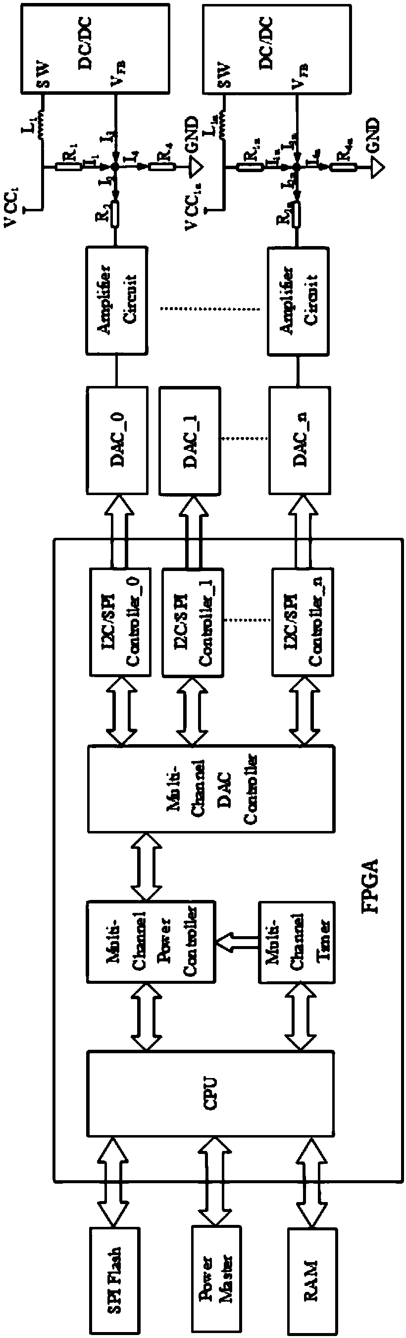
[0026] A method for testing the rise time of a power supply with an FPGA-based control module The system block diagram is as follows figure 1 shown. According to Kirchhoff's current law, I 1 +I 3 =I 2 +I 4 , namely I 1 =I 2 +I 4 -I 3 , so as to obtain the DC / DC output voltage VCC 1 .

[0027] VCC 1 =I 1 *R 1 +V FB =(I 2 +I 4 -I 3 )*R 1 +V FB

[0028] Among them, V FB Feedback Voltage (feedback voltage)...


PUM


Abstract

The invention relates to the technical field of a display module, in particular to a method and a device for controlling the rise time of a module testing power supply. Based on the multi-channel independent control of an editable gate array, the control process comprises the steps of after receiving a power-on command, triggering a timer of each channel for timing; and when any channel reaches the timing interval corresponding to the timer of the channel, sending a timing interruption corresponding to the channel number of the channel; receiving the timing interruption and sending a steppingvoltage value to the channel corresponding to the timing interrupt; and accumulating the stepping voltage value received by each channel each time, and outputting the accumulated voltage values. Taskscheduling is performed by use of a CPU (Central Processing Unit) embedded in an FPGA (Field Programmable Gate Array), and the high-speed parallel power-on time and waveform control are implemented through the multi-channel independent hardware control logic.

Description

technical field [0001] The invention relates to the technical field of display modules, in particular to a method and a device for controlling the rise time of a module test power supply. Background technique [0002] When display module manufacturers conduct power-on point-screen tests on LCM, OLED and other display modules, the module IC has strict requirements on the rise time of the test power supply, otherwise the module may work abnormally or even be damaged. [0003] Usually, the method of testing the rising time of the power supply with a single-chip microcomputer control module is slow, the waveform is poor, and the time accuracy is low. Moreover, due to the seriality of its execution instructions, it is impossible to guarantee the real-time performance of multiple channels of the test module to test the power supply. Responsiveness, precision and parallelism. Contents of the invention [0004] In order to solve the above-mentioned technical problems, the object ...

Claims


Application Information

Patent Timeline
IPC IPC(8): G05B19/042G06F13/42
CPCG05B19/0421G05B19/0423G05B2219/21137G05B2219/2214G05B2219/25028G06F13/4282
Inventor 叶金平杨志浩白静刘荣华
Owner WUHAN JINGCE ELECTRONICS GRP CO LTD
Why Eureka
Try Eureka