Horizontal spraying production line

A production line, horizontal technology, applied in spray booths, spray devices, etc., can solve the problems of low operation efficiency, thick coating thickness, complicated steps, etc., and achieve the effects of simple structure, improved uniformity, and reduced manufacturing costs.

Pending Publication Date: 2019-10-15
东莞市驰铭智能科技有限公司
View PDF0 Cites 6 Cited by
  • Summary
  • Abstract
  • Description
  • Claims
  • Application Information

AI Technical Summary

Problems solved by technology

[0003] Large-scale spraying operations are usually completed on the spraying production line. At present, there is a spraying production line, which includes a conveying chain, a spraying room and a drying room, etc. The conveying chain is connected with suspended fixtures distributed at intervals. It is installed on the hanging jig, and the conveying chain drives the workpiece to pass through the spraying room and the drying room in turn to complete the spraying and drying operations of the paint, and the spraying room and the drying room are also equipped with a rotating drive device, so that it can be sprayed or dried during spraying or drying. Drive the workpiece to rotate around its own vertical axis when it is dry; during the spraying process of this spraying production line, due to the influence of gravity, when it is just sprayed on the surface of the workpiece, part of the paint will flow down along the surface of the workpiece, so that when the job is completed After that, there is usually a problem that the closer to the lower end of the workpiece, the thicker the coating thickness is.
[0004] In order to improve the above situation, some manufacturers have developed a horizontal spraying equipment; this horizontal spraying equipment is equipped with multiple sets of clamping fixtures for horizontally clamping workpieces, and each set of clamping fixtures includes The static clamping module and the dynamic clamping module of the workpiece, the static clamping module includes a rotatable horizontally arranged main shaft, and the dynamic clamping module includes a rotatable horizontally arranged driven shaft and a drive driven shaft close to or away from the main shaft Sliding drive device; before spraying, drive the driven shaft to move away from the main shaft, then put the workpiece between the main shaft and the driven shaft, then drive the driven shaft close to the main shaft to clamp the workpiece, and finally drive it through the main shaft The workpiece is rotated so that the workpiece is fully sprayed; this horizontal spraying equipment can effectively avoid the problem of uneven coating thickness caused by gravity because the workpiece rotates around the horizontal axis during spraying; however, this Because each set of clamping fixtures of the horizontal spraying equipment needs to be equipped with an independent sliding drive device, its structure is often complicated; and when using this horizontal spraying equipment on the spraying production line, it is first necessary to transport the workpiece from the Remove the workpiece from the chain, and then clamp the workpiece on the clamping fixture in turn for spraying. After the spraying is completed, the workpiece needs to be removed from the clamping fixture, and then put on the conveyor chain for transportation to the next process. The steps are relatively cumbersome, so the work efficiency is often not high when using this horizontal spraying equipment

Method used


Image

  • Horizontal spraying production line
  • Horizontal spraying production line
  • Horizontal spraying production line

Examples


Embodiment Construction

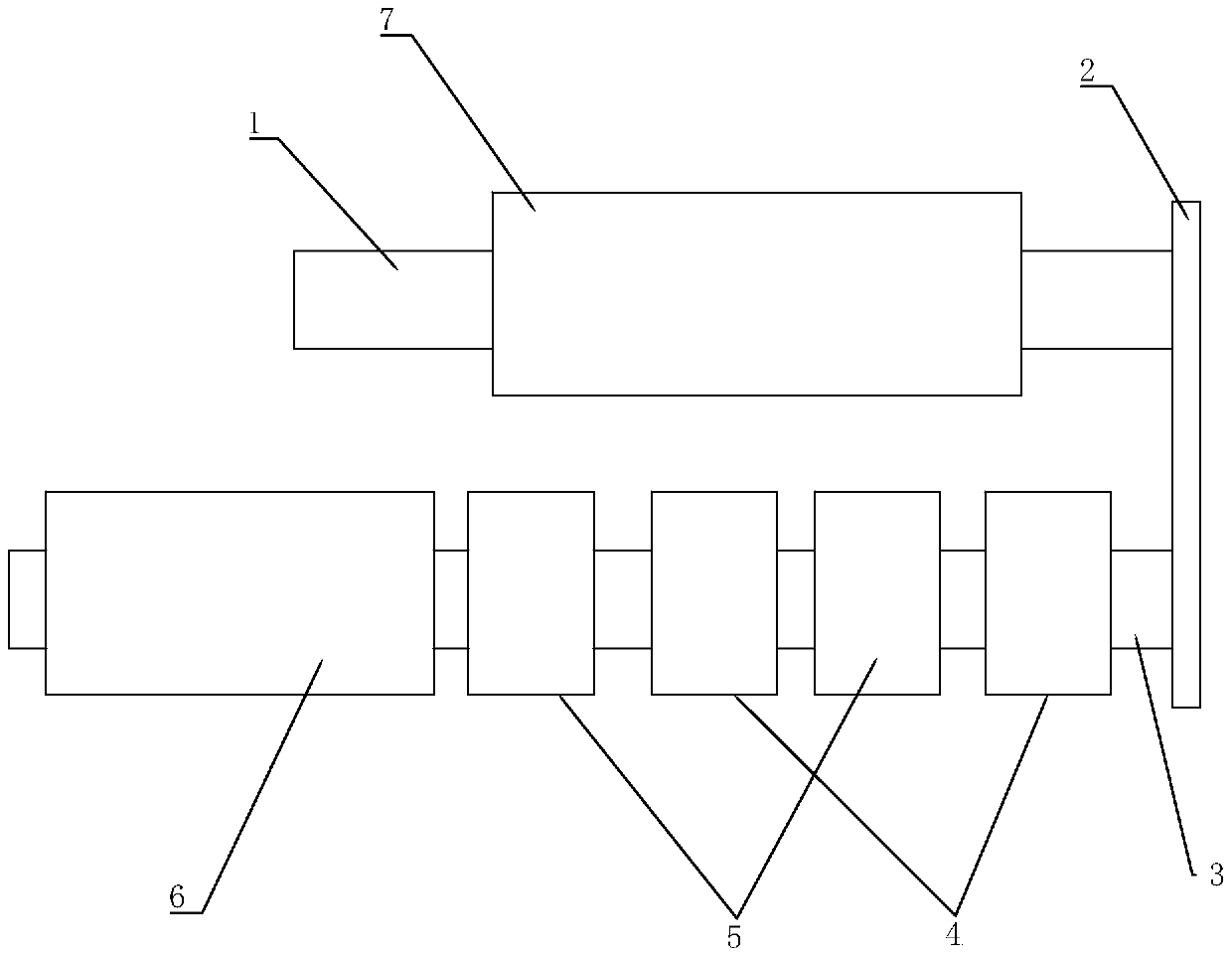
[0030] refer to figure 1 , the embodiment of the present invention provides a horizontal spraying production line, including a spraying chamber 4, a drying chamber 5, and a spraying conveying device 3 passing through the spraying chamber 4 and the drying chamber 5.

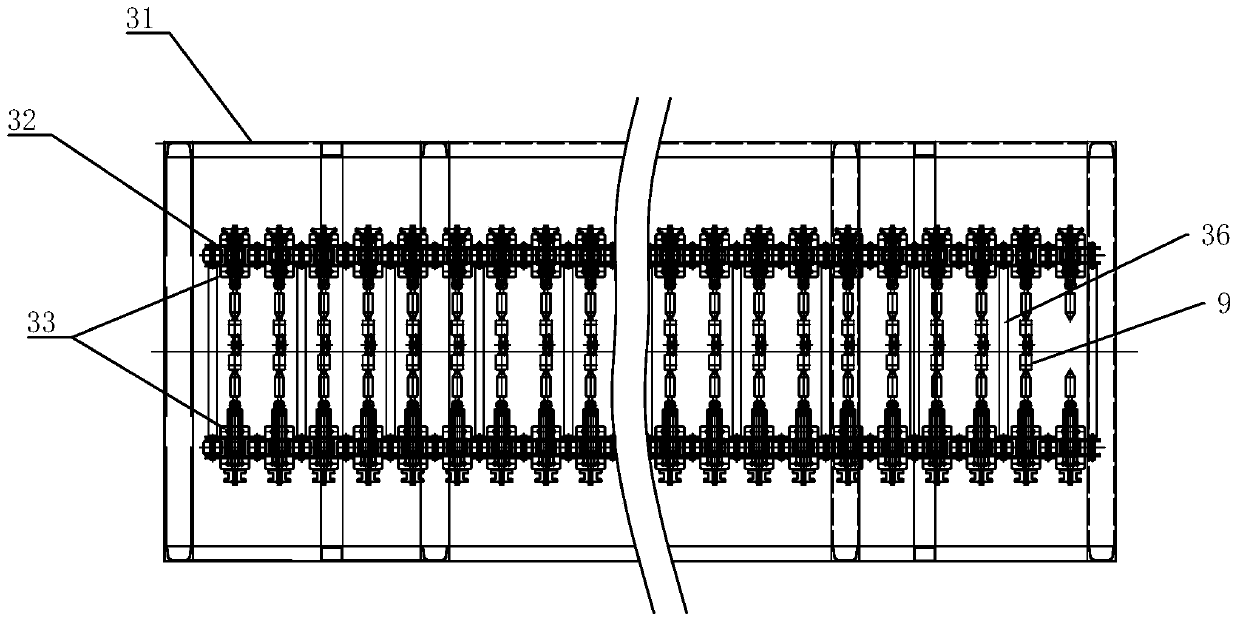
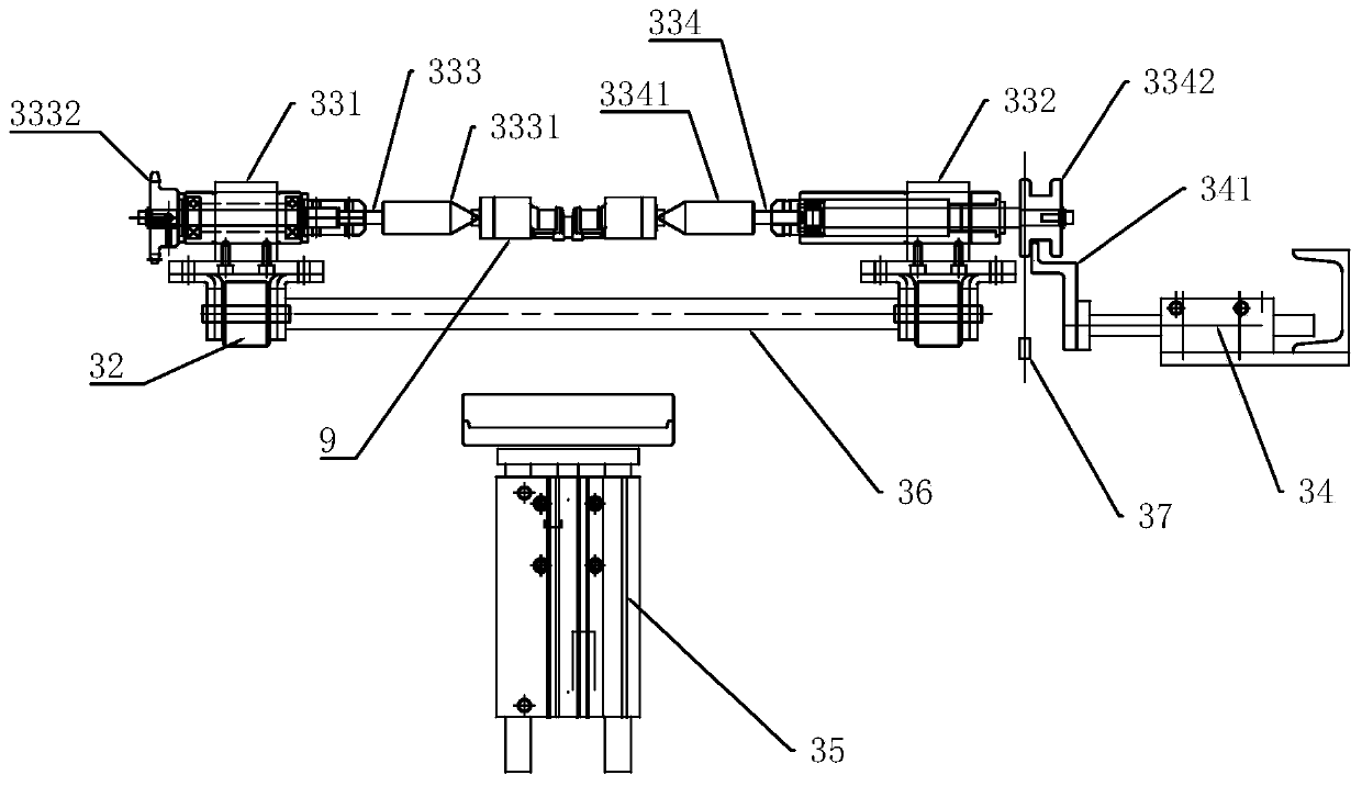
[0031] refer to Figure 2 to Figure 4, the spraying conveying device 3 includes a spraying frame 31, a spraying conveying chain 32 arranged on the spraying frame 31, a number of clamping fixtures 33 arranged on the spraying conveying chain 32, driving the spraying The first driving device (not shown in the drawings) of the conveyor chain 32 movement; in this embodiment, preferably, the first driving device includes a first motor and a driving sprocket and a driven sprocket, the The spraying conveyor chain 32 is wound on the driving sprocket and the driven sprocket. There are two spraying conveyor chains 32 arranged in parallel and at intervals; the clamping fixtures 33 all include a first mounting seat 331 and a...


PUM


Abstract

The invention discloses a horizontal spraying production line. The horizontal spraying production line comprises a spraying chamber, a drying chamber and a spraying conveying device, wherein the spraying conveying device comprises a spraying machine frame, two spraying conveying chains which are arranged in parallel at intervals and a clamping jig; the clamping jig comprises a first mounting seatand a second mounting seat; the first mounting seat and the second mounting seat are oppositely positioned on the two spraying conveying chains respectively; the first mounting seat is connected witha main shaft; one end of the main shaft is provided with a fixed pressing block, and another end of the main shaft is provided with a driving wheel; the second mounting seat is connected with a drivenshaft; one end of the driven shaft is provided with a movable pressure block; the second mounting seat is provided with a return spring which can drive the driven shaft to return to one side close tothe main shaft; the spraying conveying chains are provided with feeding positions and discharging positions; the feeding positions and the discharging positions are both provided with second drivingdevices for pulling the driven shaft to slide; and the spraying chamber is provided with a rotary driving device for driving the driving wheel to rotate. The horizontal spraying production line not only can ensure uniform spraying for workpieces, but also has higher working efficiency and simple structure.

Description

technical field [0001] The invention relates to the technical field of spraying equipment, in particular to a horizontal spraying production line. Background technique [0002] Many products need to be sprayed with a layer of coating on their surface to improve the performance of the product. For example, the piston of an automobile air-conditioning compressor is coated with a layer of tetrafluoroethylene wear-resistant material. This is because PTFE Ethylene has good wear resistance and compactness, which can reduce the clearance volume on the surface of the piston and make the piston have good air tightness, thereby improving the working efficiency and service life of the automotive air-conditioning compressor. [0003] Large-scale spraying operations are usually completed on the spraying production line. At present, there is a spraying production line, which includes a conveying chain, a spraying room and a drying room, etc. The conveying chain is connected with suspensio...

Claims


Application Information

Patent Timeline
Patent Type & Authority Applications(China)
IPC IPC(8): B05B16/20B05B13/02
CPCB05B16/20B05B16/95
Inventor 李智民
Owner 东莞市驰铭智能科技有限公司
Why Eureka
Try Eureka