Integrated horizontal axial flow pump station and application thereof

A technology of axial flow pump and axial flow, which is applied in pumping stations, buildings, water supply devices, etc., can solve the problems of long construction period, shortened service life of pumping stations, and high failure of components, so as to reduce construction cost and maintenance cost, Reduced operating costs and extended service life

Pending Publication Date: 2019-10-15
华南泵业(赣州)有限公司
View PDF0 Cites 0 Cited by
  • Summary
  • Abstract
  • Description
  • Claims
  • Application Information

AI Technical Summary

Problems solved by technology

[0004] (1) Long construction period, large investment of manpower and material resources, and large floor area: the traditional concrete pumping station is a steel concrete structure, and the bottom plate, pool wall, roof, runner, and forebay of the pumping station are constructed, poured and maintained step by step It takes 2-3 months, and the construction period is very long; due to the concrete structure and construction restrictions, the concrete pump room occupies a large area; and because the manpower required for civil engineering is relatively large, with the increase in labor costs and material costs, concrete The construction cost of the pumping station is also very high
[0005] (2) The number of suppliers is large, the degree of component coordination is low, and accountability and maintenance are difficult: the construction of the pumping station and the provision of equipment are different suppliers, and the mutual cooperation between the suppliers and the civil engineering party is relatively poor; The components are assembled together, and the matching degree is poor, resulting in a high probability of failure between components, and at the same time, it cannot meet the optimal hydraulic waterway design of the pumping station, resulting in uncoordinated operation of the entire pumping station sys

Method used


Image

  • Integrated horizontal axial flow pump station and application thereof

Examples


Example Embodiment

[0024] The application will be further introduced below in conjunction with embodiments.

[0025] In order to explain the embodiments of the present invention or the technical solutions in the prior art more clearly, in the following description, different "one embodiment" or "embodiment" do not necessarily refer to the same embodiment. Different embodiments can be substituted or combined. For those of ordinary skill in the art, other implementation manners can be obtained based on these embodiments without creative work.

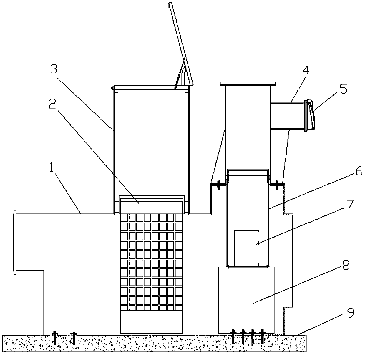
[0026] In order to reduce the construction and maintenance cost of the pumping station, and at the same time extend the service life of the pumping station, the applicant has made extensive research and improved the existing pumping station. Firstly, it explored and developed a FRP integrated axial flow pumping station. The vertical glass fiber reinforced plastic wellbore is used as the suction well of the pump, and then a concrete forepool is set at the inlet e...


PUM


Abstract

The invention belongs to the technical field of water conservancy engineering. In order to solve the problems of high construction cost and high maintenance cost of the current pump station, an integrated horizontal axial flow pump station and application thereof are disclosed. The pump station comprises a horizontally-arranged water collecting wellbore, a grille upper wellbore and a water pump upper wellbore; the grille upper wellbore is a vertical grille upper wellbore, and the lower end of the grille upper wellbore is in communication with the upper part of the water collecting wellbore; agrille is arranged at the communication position of the grille upper wellbore and the water collecting wellbore; the water pump upper wellbore is a vertical water pump wellbore, and the lower end of the water pump upper wellbore is in communication with the upper part of the water collecting wellbore; a submersible axial flow pump is arranged at the communication position of the water pump upper wellbore and the water collecting wellbore; and the upper portion of the water pump upper wellbore is provided with an outlet flap valve. The pump station has the advantages of low cost and convenientmaintenance.

Description

technical field [0001] The invention relates to the technical field of water conservancy engineering, in particular to an integrated horizontal axial flow pumping station and its application. Background technique [0002] The description of the background technology of the present invention belongs to the relevant technology related to the present invention, and is only used to illustrate and facilitate the understanding of the content of the present invention. prior art on the filing date. [0003] Traditional axial-flow pumping station: usually an axial-flow pumping house made of concrete, in which the hydraulic construction includes an axial-flow pumping station and a forebay of the pumping station. The construction of this traditional pumping station is very difficult, and the construction of the pumping station The complex structure mainly has the following disadvantages: [0004] (1) Long construction period, large investment of manpower and material resources, and l...

Claims


Application Information

Patent Timeline
IPC IPC(8): E03B5/04E03B5/06
CPCE03B5/04E03B5/06
Inventor 赖华煌龚伟赖华斌蓝风翔
Owner 华南泵业(赣州)有限公司
Why Eureka
Try Eureka