Eureka AIR delivers breakthrough ideas for toughest innovation challenges, trusted by R&D personnel around the world.

Hydraulic door type self-flushing device for rainwater storage pond

A storage tank and self-flushing technology, which is applied to water supply devices, waterway systems, drainage structures, etc., can solve the problems of high operation and maintenance costs, high device costs, and difficult construction, and achieve low operation and maintenance costs and low device costs , the effect of improving the service life

Pending Publication Date: 2019-10-15
JIANGSU HUARUI SPONGE CITY CONSTR CO LTD
View PDF1 Cites 1 Cited by
  • Summary
  • Abstract
  • Description
  • Claims
  • Application Information

AI Technical Summary

Problems solved by technology

The above-mentioned patent controls the opening or closing of the flushing door through the hydraulic control cabinet, so it involves the hardware and software design of the hydraulic control cabinet, which is difficult to construct and maintain, and the equipment cost is high, which will lead to Higher cost of drainage
[0004] In order to overcome the deficiencies and defects in the background technology, the present invention provides a hydraulic door-type self-flushing device for rainwater storage tanks, which can solve the problems of high device cost and high operation and maintenance cost in the prior art

Method used


Image

  • Hydraulic door type self-flushing device for rainwater storage pond
  • Hydraulic door type self-flushing device for rainwater storage pond
  • Hydraulic door type self-flushing device for rainwater storage pond

Examples


Embodiment Construction

[0059] The following will clearly and completely describe the technical solutions in the embodiments of the present invention with reference to the accompanying drawings in the embodiments of the present invention. Obviously, the described embodiments are only some, not all, embodiments of the present invention.

[0060] Examples of the described embodiments are shown in the drawings, wherein like or similar reference numerals designate like or similar elements or elements having the same or similar functions throughout. The embodiments described below by referring to the figures are exemplary and are intended to explain the present invention and should not be construed as limiting the present invention.

[0061]In describing the present invention, it should be understood that the terms "center", "longitudinal", "transverse", "length", "width", "thickness", "upper", "lower", "front", " Back", "Left", "Right", "Vertical", "Horizontal", "Top", "Bottom", "Inner", "Outer", "Clockw...


PUM


Abstract

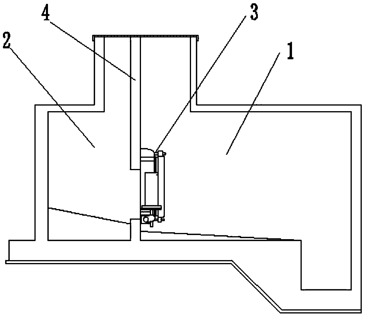
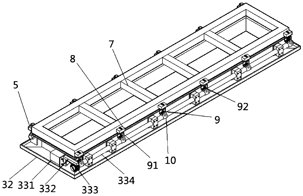
The invention discloses a hydraulic door type self-flushing device for a rainwater storage pond. The hydraulic door type self-flushing device comprises a storage pond and a water storage chamber whichare separated by a partition plate. A hydraulic flushing door for opening or closing a flushing port is correspondingly arranged on the top of the partition plate, the hydraulic flushing door comprises a flushing door plate, a flushing door frame and a hydraulic transmission mechanism, the flushing door plate is mounted at the top end of the flushing door frame through a coupling hinge, the flushing door plate rotates relative to the flushing door frame to open or close the hydraulic flushing door, the hydraulic transmission mechanism is mounted at the bottom end of the flushing door frame, and the hydraulic transmission mechanism locks or loosens the flushing door plate to open or close the hydraulic flushing door. The invention provides the hydraulic door type self-flushing device. Thehydraulic transmission mechanism is arranged on the flushing door frame, a transmission shaft is driven by the hydraulic oil cylinder to rotate to drive a hook to lock or be separated from a lock catch on the flushing door plate, and the flushing door plate rotates relative to the flushing door frame to open or close the flushing door, so that the whole action is coherent and stable, and the workefficiency is improved greatly.

Description

technical field [0001] The invention relates to the technical field of rainwater treatment, in particular to a hydraulic door-type self-flushing device for a rainwater storage tank. Background technique [0002] Since the storage water of the rainwater storage tank has the characteristics of high concentration of suspended particles and high concentration of organic pollutants, after the sewage stays in the tank for several hours, the pollutants and impurities in the water will be deposited. Therefore, after the rainwater storage tank is emptied, the storage tank A certain thickness of silt will accumulate at the bottom, which not only occupies a limited volume of the pool, but also emits odor and causes corrosion damage to facilities and equipment. In order to eliminate the above-mentioned adverse effects, the sediment at the bottom of the pool needs to be effectively washed in time after the rainwater storage tank is emptied Desilting, therefore, effective flushing and rem...

Claims


Application Information

Patent Timeline
Patent Type & Authority Applications(China)
IPC IPC(8): E03F5/10
CPCE03F5/10E03F5/108E03F5/105
Inventor 周春华
Owner JIANGSU HUARUI SPONGE CITY CONSTR CO LTD
Why Eureka
Eureka Blog
Learn More