Passive type permanent magnet repulsion type magnetic bearing structure

A passive, magnetic bearing technology, applied in the direction of bearings, shafts, bearings, mechanical equipment, etc., can solve the problems of high control precision, large system power consumption, complex structure, etc., and achieve stable rotor rotation, reduce loss, and small volume Effect

Active Publication Date: 2019-10-15
SHANDONG UNIV OF SCI & TECH
View PDF6 Cites 5 Cited by
  • Summary
  • Abstract
  • Description
  • Claims
  • Application Information

AI Technical Summary

Problems solved by technology

Most of the magnetic bearings currently studied are active and hybrid, with complex structures, large sizes, high requirements for control accuracy, and relatively large power consumption of the system.

Method used


Image

  • Passive type permanent magnet repulsion type magnetic bearing structure
  • Passive type permanent magnet repulsion type magnetic bearing structure
  • Passive type permanent magnet repulsion type magnetic bearing structure

Examples


Embodiment 1

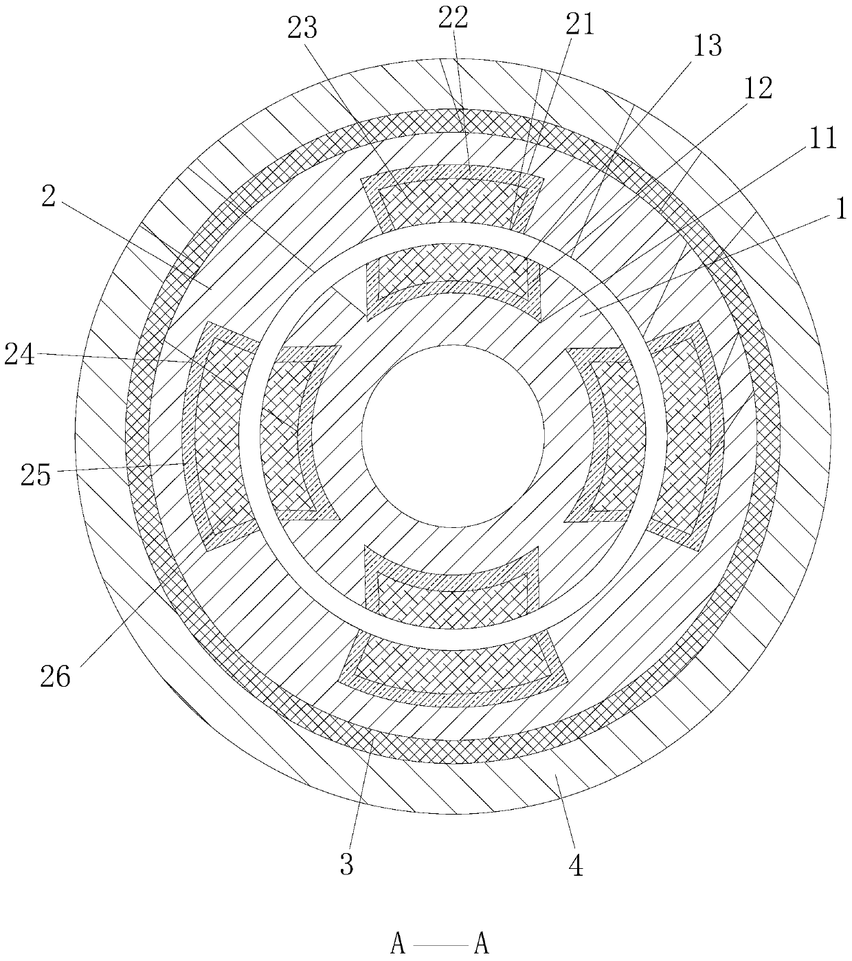
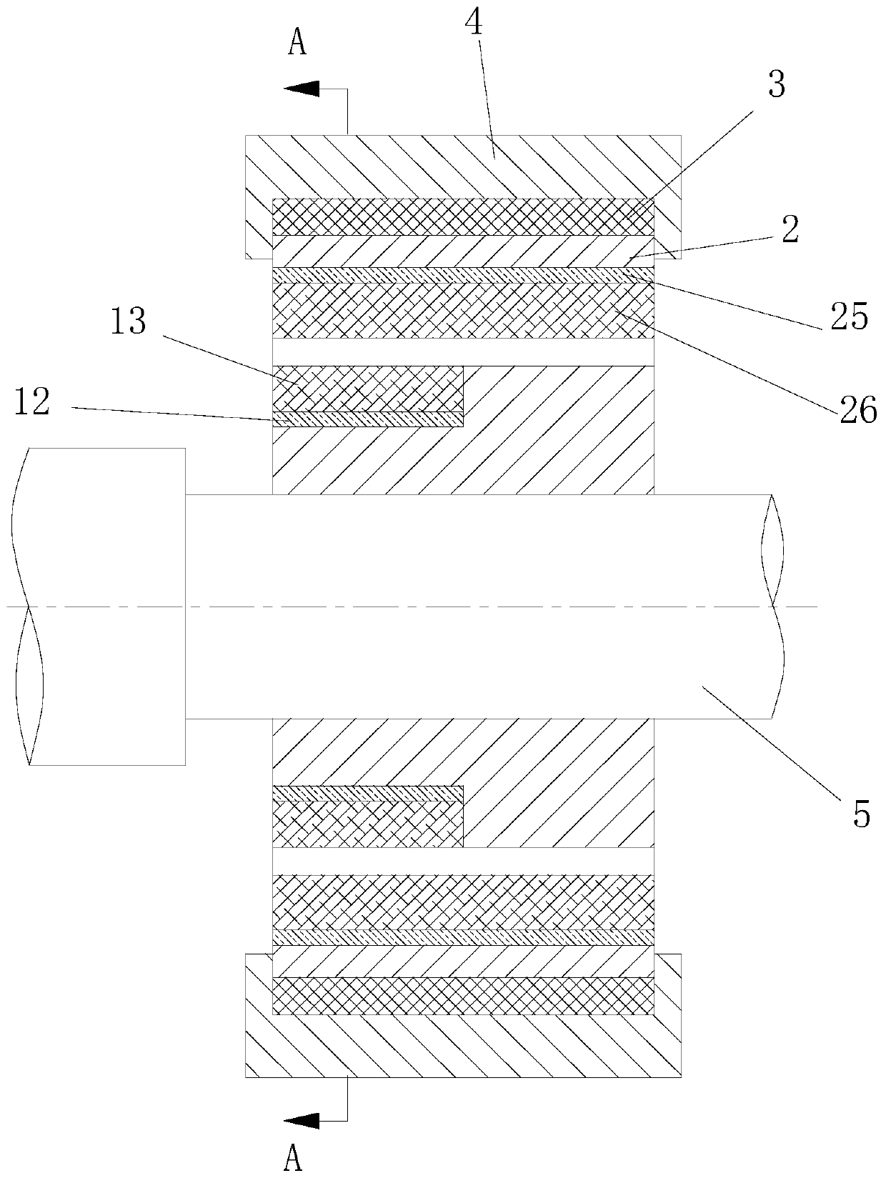
[0074] The above-mentioned magnetic bearing structure, the magnetic bearing composed of the stator 2 and the rotor 1, is mainly used to provide radial bearing capacity.

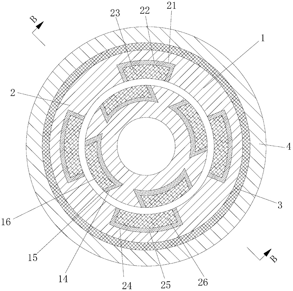
[0075] The force between the stator 2 and the rotor 1 is the repulsive force generated between the first rotor permanent magnet 13 , the second rotor permanent magnet 16 , the first stator permanent magnet 23 and the second stator permanent magnet 26 .

[0076] Its magnetic field lines are as Figure 7 and Figure 8 shown. Wherein the first stator permanent magnet 23 is positioned at the upper side in the stator 2, the second stator permanent magnet 26 is compared with the first stator permanent magnet 23, and the magnet area corresponding to the second stator permanent magnet 26 and the rotor permanent magnet is large, Therefore, the generated repulsive force is relatively large, which can offset the gravity of the rotating shaft itself, so that the air gap between the rotor 1 and the stator 2 is evenly di...

Embodiment 2

[0078] The radial force of the magnetic bearing varies with the size of the air gap. When the axial air gap of the two magnets decreases, the force at the place where the air gap decreases becomes larger, otherwise the radial force decreases.

[0079] Power is provided by an external motor to drive the rotating shaft and the rotor part of the bearing to rotate. During the rotation of the bearing rotor, when the stator on the left side of the bearing and the permanent magnet of the rotor are completely opposite, the stator on the right side of the bearing and the permanent magnet of the rotor are completely staggered, as figure 1 and image 3 As shown, the radial force required by the bearing at this time is completely the repulsion force generated by the left permanent magnet;

[0080] When the bearing rotor rotates at a certain angle, the permanent magnets on the left and right sides of the bearing are partially distributed, and the sum of the relative areas of the permanent ...

Embodiment 3

[0084] The principle of the present invention is: the magnetic force lines of the permanent magnet pass through the air gap and the magnetic isolation sheet to form a circuit to provide a magnetic field for the magnetic bearing and bear the radial force on the magnetic bearing;

[0085] Wherein the first stator permanent magnet of the stator is located on the upper side in the middle of the stator, and the second stator permanent magnet of the stator is compared with the first permanent magnet, and the magnet area corresponding to the second permanent magnet and the rotor permanent magnet is larger, and the repulsive force generated Relatively large, so it can offset the gravity of the shaft itself.

[0086] When there is external interference, the distance between the bearing rotor and the bearing stator will change, the size of the air gap will decrease or increase accordingly, and the corresponding repulsion force will also increase or decrease accordingly, and the force on ...


PUM


Abstract

The invention discloses a passive type permanent magnet repulsion type magnetic bearing structure. The passive type permanent magnet repulsion type magnetic bearing structure comprises a rotor and a stator. A plurality of first rotor grooves are formed in the outer wall of the front half portion of the rotor. First rotor magnetism isolating sheets and first rotor permanent magnets are arranged inthe first rotor grooves. A plurality of second rotor grooves are formed in the outer wall of the rear half portion of the rotor. Second rotor magnetism isolating sheets and second rotor permanent magnets are arranged in the second rotor grooves. The stator sleeves the rotor. A gap is formed between the stator and the rotor. A first stator groove is formed in the upper inner end wall of the stator.A first stator magnetism isolating sheet and a first stator permanent magnet are arranged in the first stator groove. Second stator grooves are formed in the left inner end wall, right inner end walland lower inner end wall of the stator. Second stator magnetism isolating sheets and second stator permanent magnets are arranged in the second stator grooves. A rubber damping ring sleeves the outerend of the stator. A bearing block sleeves the outer end of the rubber damping ring. The passive type permanent magnet repulsion type magnetic bearing structure is provided with the rubber damping ring, and is simple in overall structure, small in size and good in vibration reduction effect.

Description

technical field [0001] The invention relates to the field of magnetic suspension bearings, in particular to a passive permanent magnetic repulsion type magnetic bearing structure. Background technique [0002] Magnetic bearing is a new type of high performance bearing. It uses magnetic force to suspend the rotor in the air, and the magnetic bearing makes there is no mechanical contact between the stator and the rotor. Compared with traditional ball bearings, sliding bearings and oil film bearings, the rotor can reach a very high speed, and has the advantages of no mechanical friction, low energy consumption, low noise, long life, no lubrication, no oil pollution, etc., especially suitable for high speed, Special environment such as vacuum. According to the working principle, magnetic bearings are mainly divided into the following three categories: active magnetic bearings, passive magnetic bearings and hybrid magnetic bearings. [0003] Active magnetic bearings use electr...

Claims


Application Information

Patent Timeline
Patent Type & Authority Applications(China)
IPC IPC(8): F16C32/04
CPCF16C32/0425
Inventor 丁鸿昌李帽顺樊玉华秦晓君巩玉春
Owner SHANDONG UNIV OF SCI & TECH
Why Eureka
Try Eureka