Supercharge Your Innovation With Domain-Expert AI Agents!

Automatic drainer

A technology of automatic drainage and drainage outlet, applied in the directions of engine components, lift valves, valve details, etc., can solve problems such as easy blockage of drainage channels, and achieve the effect of avoiding blockage

Pending Publication Date: 2019-10-15
浙江厚德气动元件有限公司
View PDF1 Cites 0 Cited by
  • Summary
  • Abstract
  • Description
  • Claims
  • Application Information

AI Technical Summary

Problems solved by technology

[0003] In this regard, the technical problem to be solved by the present invention is the problem that the drainage channel of the existing automatic drain is easily blocked

Method used


Image

  • Automatic drainer
  • Automatic drainer
  • Automatic drainer

Examples


Embodiment Construction

[0020] Below in conjunction with accompanying drawing, concrete structure among the present invention is described:

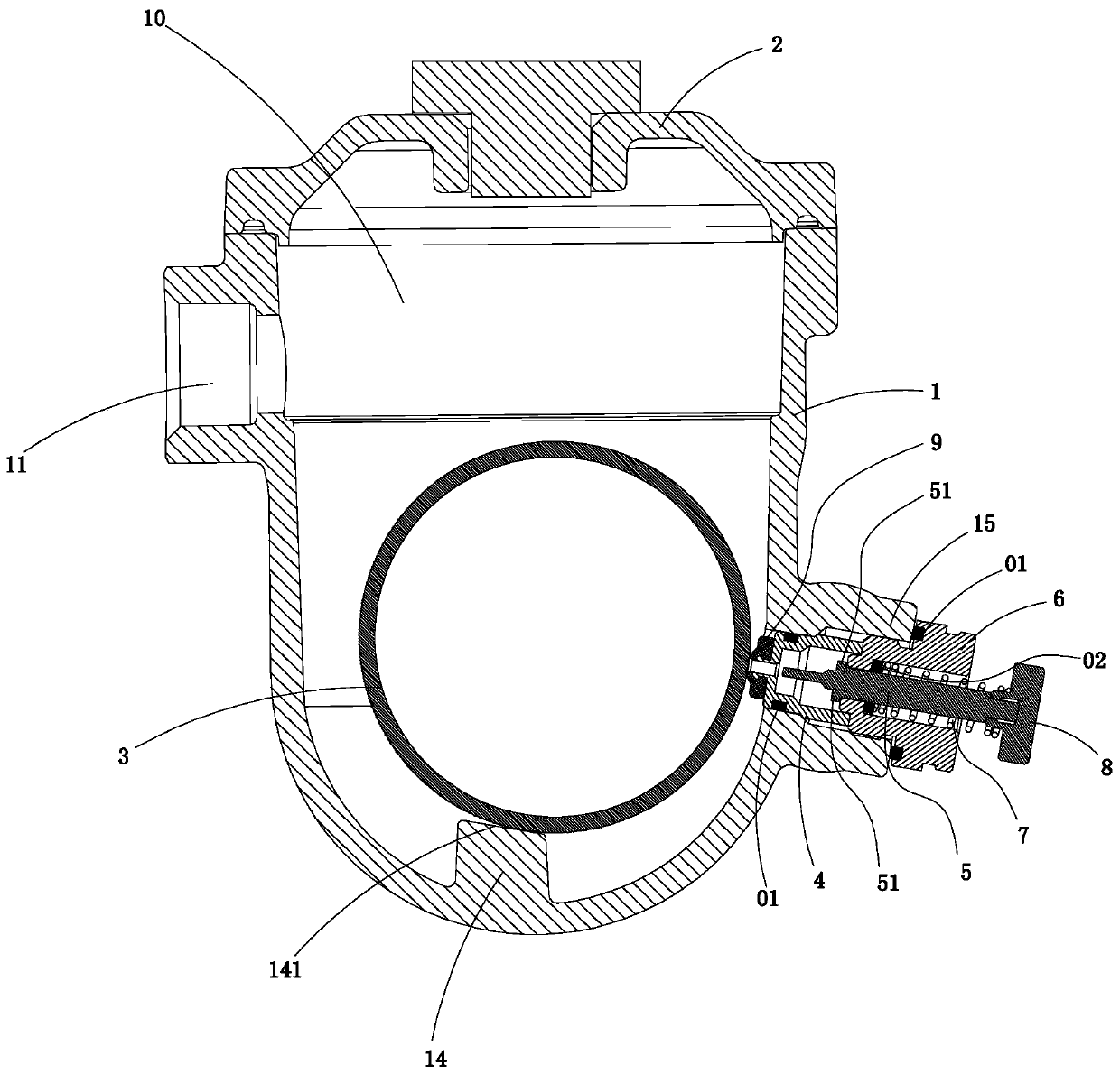
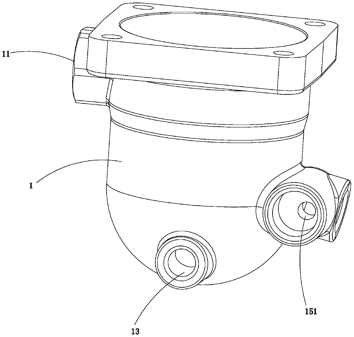
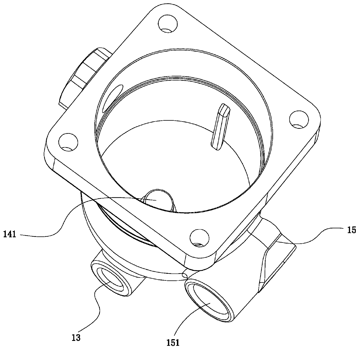
[0021] An automatic drain, such as Figure 1 to Figure 3 As shown, it includes a housing 1 with a cavity 10, a housing cover 2 arranged on the upper part of the housing 1 and a float 3 arranged in the housing 1, and the upper part of the housing 1 is provided with a water inlet 11. The bottom is provided with a drain port 12, the bottom of the cavity 10 is provided with a support boss 14, and the top of the support boss 14 is provided with a guide slope 141; the outer wall of the housing 1 is connected with the drain port 12 The corresponding position is formed with a pipe body 15, and the side wall of the pipe body 15 is provided with a drain hole 151; the pipe body 15 is provided with a dredging assembly, and the dredging assembly includes a valve nozzle 4, a thimble 5, and a needle seat 6 , spring 7 and button 8, the valve mouth 4 is fixed on the inner end ...


PUM


Abstract

The invention discloses an automatic drainer. The automatic drainer comprises a shell, a shell cover and a floating ball, wherein a water inlet is formed in the upper part of the shell; a water outletis formed in the bottom of the shell; a support boss is arranged at the bottom of a cavity; a guide slope is arranged at the top of the support boss; a pipe body is formed on the outer wall of the shell; a drainage hole is formed in the side wall of the pipe body; a dredging assembly is arranged in the pipe body; the dredging assembly comprises a valve nozzle, a thimble, a thimble seat, a springand a button; the valve nozzle is fixed to the inner end part in the pipe body; a drainage channel communicating with the cavity is formed in the valve nozzle; the drainage channel communicates with the drainage hole; the thimble seat is fixed to the outer end part in the pipe body; the thimble is movably arranged on the thimble seat; the button is connected with the outer end of the thimble; andthe thimble can be pushed to move inward when inward stress is applied on the button, and can move outward to restore under the elastic force of the spring when the stress applied on the button is removed. The automatic drainer is reasonable in structure and capable of achieving automatic drainage; and the dredging is carried out through the dredging assembly to avoid blockage of the drainage channel.

Description

technical field [0001] The invention relates to an automatic drainer, which belongs to the field of drainer structural design. Background technique [0002] Patent document CN206361902U discloses a drainer, including a main cavity, the bottom side wall of the main cavity is provided with a sewage outlet, and a sewage plug with a sealing ring is installed; the lower part of one side of the main cavity is provided with a water inlet A water outlet hole is opened at the bottom of the main cavity; a sealed floating ball is placed at the water outlet hole; the water inlet hole is connected to a horizontal water inlet pipe, and the water outlet hole is connected to a horizontal water outlet pipe. When the drainer in this patent document is in use, the light-weight sealed floating ball inside the main cavity is used. When the condensed water flows through, the sealed floating ball is floated by the buoyancy of the water, and the condensed water is discharged smoothly. When the cond...

Claims


Application Information

Patent Timeline
Patent Type & Authority Applications(China)
IPC IPC(8): F16K31/20F16K1/14F16K1/32F16K27/02
CPCF16K31/20F16K1/14F16K1/32F16K27/0245
Inventor 黄顺利周俊杰梁兴龙吴光辉
Owner 浙江厚德气动元件有限公司
Features
  • R&D
  • Intellectual Property
  • Life Sciences
  • Materials
  • Tech Scout
  • Unparalleled Data Quality
  • Higher Quality Content
  • 60% Fewer Hallucinations
Learn More