Supercharge Your Innovation With Domain-Expert AI Agents!

Automatic condensate water collecting and discharging system and device of radioactive gas sampling pipeline

A radioactive gas, automatic collection technology, used in pipeline systems, measuring devices, lubrication indicating devices, etc., can solve the problems of personnel being injured by radiation, damage to instruments, and waste a lot of time, to eliminate instrument damage events, reduce workload, To achieve the effect of continuous operation

Pending Publication Date: 2021-06-22
JIANGSU NUCLEAR POWER CORP
View PDF0 Cites 0 Cited by
  • Summary
  • Abstract
  • Description
  • Claims
  • Application Information

AI Technical Summary

Problems solved by technology

[0003] Since many process systems in nuclear power plants are connected to heat sources, the gas medium sampled from the process system usually has a relatively high temperature. However, the current dewatering device needs to be isolated and out of service for instrument sampling monitoring and needs to be regularly visited by the system operator. Some areas are radiation-contaminated areas, and the water needs to be drained manually on the spot, and the operator will spend a lot of time. Time is used for the drainage of the on-site gas sampling and water removal device, and there is a risk of personnel being injured by radiation. In addition, there is a situation where condensed water enters the instrument and damages the instrument if it is not drained in time

Method used


Image

  • Automatic condensate water collecting and discharging system and device of radioactive gas sampling pipeline
  • Automatic condensate water collecting and discharging system and device of radioactive gas sampling pipeline
  • Automatic condensate water collecting and discharging system and device of radioactive gas sampling pipeline

Examples


Embodiment 1

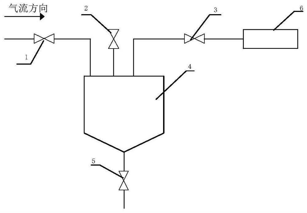
[0074] Such as figure 1 As shown, it is a radioactive gas sampling pipeline dewatering device in the prior art, including V1 manual isolation valve 1, V2 manual atmospheric communication isolation valve 2, V3 manual isolation valve 3, T1 gas sampling dewatering device 4, and V4 manual drainage isolation Valve 5 and gauge 6. One end of V1 manual isolation valve 1 is connected with the radioactive gas sampling pipeline, the other end of V1 manual isolation valve 1 is connected with the inlet of T1 gas sampling dewatering device 4; one end of V2 manual atmospheric communication isolation valve 2 is connected with T1 gas sampling dewatering device The top of 4 is connected, the other end of V2 manual atmospheric communication isolation valve 2 is connected with the atmosphere; one end of V3 manual isolation valve 3 is connected with the inlet of T1 gas sampling and water removal device 4, and the other end of V3 manual isolation valve 3 is connected with instrument 6; One end of ...

Embodiment 2

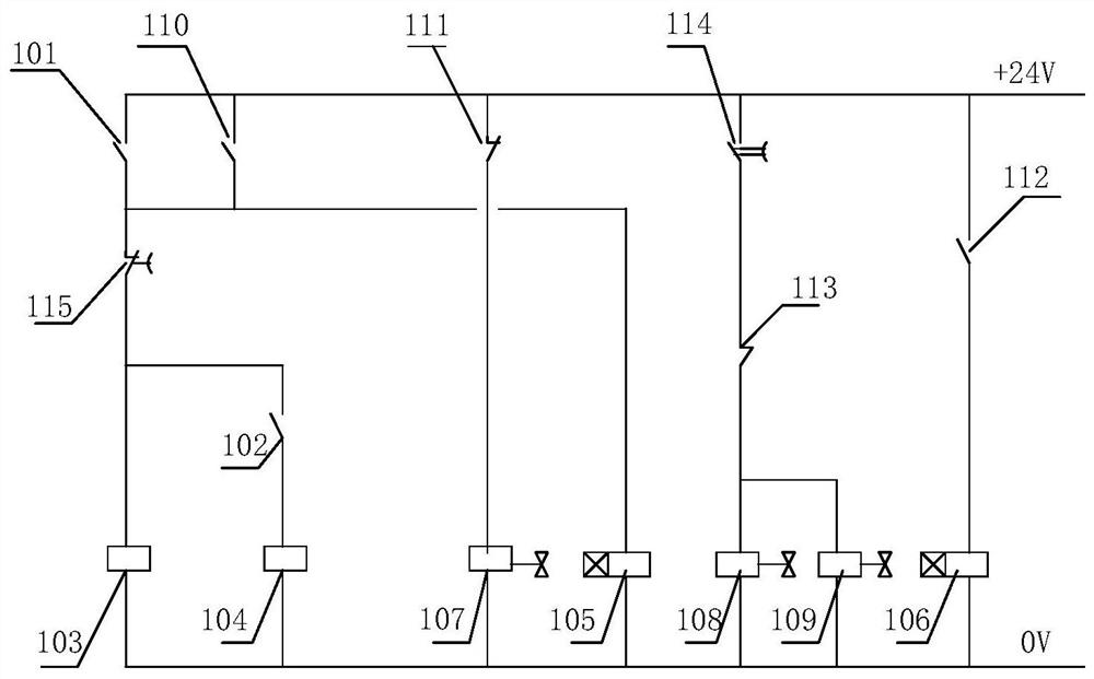
[0081] Such as figure 2 As shown, the present invention provides an automatic condensate collection and discharge system for radioactive gas sampling pipelines, including a liquid level monitoring unit, a collection control unit, a drainage control unit and a timing unit.

[0082] Liquid level monitoring unit, the output end of the liquid level monitoring unit is respectively connected to the input end of the collection control unit and the input end of the drainage control unit, monitors the liquid level signal of the condensed water and outputs the liquid level signal to the collection control unit and the drainage control unit respectively unit.

[0083] The liquid level monitoring unit includes T2 condensate water storage tank ultrasonic liquid level gauge high liquid level H signal contact switch 101, KT2 time relay normally closed contact group KT2-NC115, KA1 relay 103, KA1 relay normally open contact group KA1 -NO110, T2 condensate storage tank ultrasonic liquid level...

Embodiment 3

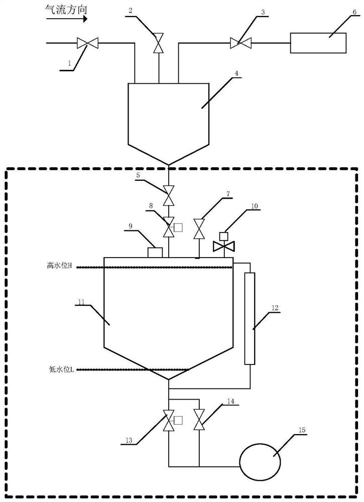
[0108] Such as image 3 As shown, the present invention provides a condensed water automatic collection and discharge device for the radioactive gas sampling pipeline, including the condensed water automatic collection and discharge system for the radioactive gas sampling pipeline of embodiment 2, including the V1 manual isolation valve 1 in the device of embodiment 1 , V2 manual atmospheric communication isolation valve 2, V3 manual isolation valve 3, T1 gas sampling and water removal device 4, V4 manual drainage isolation valve 5 and instrument 6, also including V4 manual isolation valve 5, V5 manual atmospheric communication isolation valve 7, V 1M Solenoid valve 8, ultrasonic liquid level gauge 9, V 2M Atmospheric communication solenoid valve 10, T2 condensate storage tank 11, visual liquid level communication device 12, V 3M Drain solenoid valve 13, V6 manual isolation valve 14 and floor drain 15.

[0109] One end of V1 manual isolation valve 1 is connected with the rad...


PUM


Abstract

The invention belongs to the field of nuclear power station radioactive gas sampling monitoring, and discloses an automatic condensate water collecting and discharging system and device for a radioactive gas sampling pipeline. The system comprises a liquid level monitoring unit, a collecting control unit and a water drainage control unit, wherein the output end of the liquid level monitoring unit is connected to the input end of the collection control unit and the input end of the drainage control unit respectively, and the liquid level monitoring unit monitors liquid level signals of condensate water and outputs the liquid level signals to the collecting control unit and the drainage control unit respectively; the collecting control unit receives the liquid level signals output by the liquid level monitoring unit and controls the collection of the condensate water according to the liquid level signals; the drainage control unit receives the liquid level signals output by the liquid level monitoring unit and controls the drainage of the condensate water according to the liquid level signals. The special condensate water collecting and discharging system based on an automatic control mode is arranged in a condensate water collecting and discharging device, and automatic collection and drainage of condensate water are achieved under the condition that sampling monitoring of a shutdown instrument is not isolated.

Description

technical field [0001] The invention belongs to the field of radioactive gas sampling and monitoring in nuclear power plants, and in particular relates to an automatic collection and discharge system and device for condensed water of a radioactive gas sampling pipeline. Background technique [0002] The nuclear power plant reactor produces radioactive gas through nuclear fission. In order to monitor the sealing of the primary circuit or the state of the process system, it is necessary to sample the gas medium from the system to the instrument for measurement by sampling. [0003] Since many process systems in nuclear power plants are connected to heat sources, the gas medium sampled from the process system usually has a relatively high temperature. However, the current dewatering device needs to be isolated and out of service for instrument sampling monitoring and needs to be regularly visited by the system operator. Some areas are radiation-contaminated areas, and the water...

Claims


Application Information

Patent Timeline
Patent Type & Authority Applications(China)
IPC IPC(8): F17D1/02F17D3/10F17D3/14F17D5/00G01F23/296
CPCF17D1/02F17D3/10F17D3/145F17D5/00G01F23/296
Inventor 徐少一刘翔顾涛张弩郭雅山廖凯锋杨丕龙李中孙小康丁强
Owner JIANGSU NUCLEAR POWER CORP
Features
  • R&D
  • Intellectual Property
  • Life Sciences
  • Materials
  • Tech Scout
  • Unparalleled Data Quality
  • Higher Quality Content
  • 60% Fewer Hallucinations
Learn More