Desulfurization wastewater zero-emission system using coal-fired flue gas semidry method to remove fluorine and chlorine

A technology for desulfurization wastewater and coal-fired flue gas, which is applied in separation methods, chemical instruments and methods, and separation of dispersed particles. It can solve the problems of difficult removal of sediment, large drop in smoke temperature, and high operating costs, and achieve low operating costs. , reduced emissions, simple system effect

Inactive Publication Date: 2016-11-09
ZHEJIANG UNIV
View PDF11 Cites 17 Cited by
  • Summary
  • Abstract
  • Description
  • Claims
  • Application Information

AI Technical Summary

Problems solved by technology

With the improvement of environmental protection awareness and requirements, zero discharge of desulfurization wastewater is gradually put on the agenda. Most of the pollutants in desulfurization wastewater can be removed by conventional low-cost methods, but Cl - However, it is difficult to remove simply because it is difficult to form sediment. The most effective technology at present is the method of evaporation, but it consumes a lot of energy, so there is a problem of high operating costs.
Conventional zero-discharge of wastewater is equivalent to zero-pollutant water discharge. At present, there are also attempts to spray desulfurization wastewater into a higher temperature flue to achieve zero-flow discharge of desulfurization wastewater. There are some outstanding problems such as large temperature drop and serious flue contamination, so it is difficult to implement effectively

Method used


Image

  • Desulfurization wastewater zero-emission system using coal-fired flue gas semidry method to remove fluorine and chlorine

Examples


Embodiment Construction

[0020] The present invention will be further described below in conjunction with accompanying drawing.

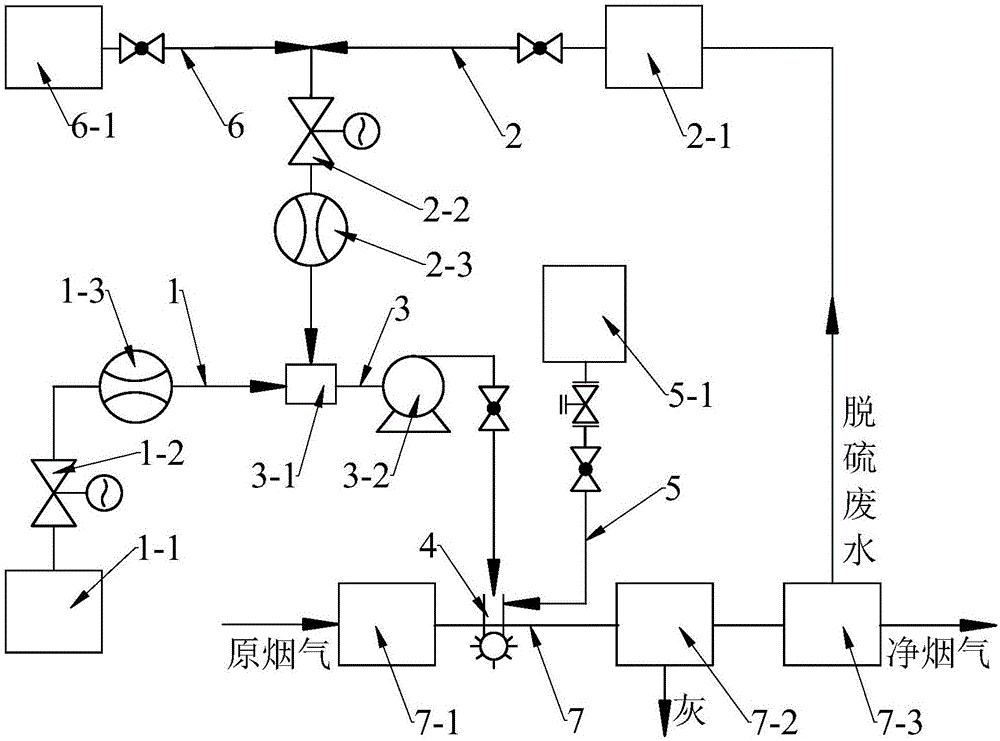
[0021] Such as figure 1 As shown, a desulfurization wastewater zero discharge system for the semi-dry removal of fluorine and chlorine from coal-fired flue gas, including a high-concentration lye pipeline 1, a desulfurization wastewater pipeline 2, a diluted lye pipeline 3, and an lye atomization device 4. Compressed air pipeline 5, process water pipeline 6 and flue 7.

[0022] The high-concentration lye pipeline 1 includes a high-concentration lye storage tank 1-1, a high-concentration lye regulating valve 1-2, and a high-concentration lye flowmeter 1-3.

[0023] The desulfurization wastewater pipeline 2 includes a desulfurization wastewater clarification tank 2-1, a desulfurization wastewater regulating valve 2-2, and a desulfurization wastewater flow meter 2-3.

[0024] The diluted lye pipeline 3 includes an lye dilution mixer 3-1 and a high-pressure pump 3-2.

[0025...


PUM


Abstract

The invention discloses a desulfurization wastewater zero-emission system using a coal-fired flue gas semidry method to remove fluorine and chlorine. The desulfurization wastewater zero-emission system comprises a high-concentration alkali liquor pipeline, a desulfurization wastewater pipeline, a diluted alkali liquor pipeline, an alkali liquor atomizing device, a compressed air pipeline, a process water pipeline and a flue. The flow of high-concentration alkali liquor is controlled according to unit load and the HCl concentration in flue gas, the high-concentration alkali liquor is mixed with desulfurization wastewater to obtain diluted alkali liquor, the diluted alkali liquor is sprayed into the flue between an air preheater and a dust remover through the alkali liquor atomizing device with multiple nozzles in grid arrangement, the diluted alkali liquor is sufficiently evenly mixed with the flue gas to solidify most of gas such as HCl, HF. SO3 and the like in the flue gas into fly ash, the emission quantity of the desulfurization wastewater is reduced greatly, the desulfurization wastewater can be sprayed into the flue as the base solvent, and zero emission of the desulfurization wastewater is achieved. The desulfurization wastewater zero-emission system has the advantages that the system is low in influence on smoke temperature, the tail flue and equipment, the tendency of fouling corrosion of the tail low-temperature flue and the equipment can be reduced effectively, the desulfurization efficiency is increased, and the system is simple, low in investment and low in operation cost.

Description

technical field [0001] The invention belongs to the technical field of energy saving and emission reduction, and relates to a zero-discharge system for desulfurization waste water for removing fluorine and chlorine by a semi-dry method of coal-fired flue gas. Background technique [0002] Coal contains elements such as sulfur, chlorine, and fluorine. When coal is burned, these elements will generate SO 2 , HCl, HF, SO 3 Gases such as HCl, HF, SO 3 Although it is trace amount, it is a strong corrosive gas, which will have adverse effects on the low-temperature flue and equipment at the tail of the boiler. HCl and HF gas can be completely removed in the wet desulfurization system, so Cl - , F - Will be enriched in the desulfurization slurry, too high concentration of Cl - , F - It will reduce the desulfurization efficiency and even poison the desulfurization slurry. At present, the desulfurization system mainly controls the Cl in the desulfurization slurry by discharging...

Claims


Application Information

Patent Timeline
Patent Type & Authority Applications(China)
IPC IPC(8): B01D53/78B01D53/68B01D53/50
CPCB01D53/502B01D53/504B01D53/68B01D53/78B01D2251/304
Inventor 杨建国赵虹赵敏
Owner ZHEJIANG UNIV
Why Eureka
Try Eureka