Supercharge Your Innovation With Domain-Expert AI Agents!

Automatic drainage device for positive pressure pipeline

An automatic drainage and pipe pressure technology, which is applied in the direction of valve devices, pipe components, engine components, etc., can solve the problems of pipeline pressure loss, affecting production safety, and inapplicability, so as to reduce the internal and external pressure difference, improve operation accuracy, The effect of simple structure

Active Publication Date: 2020-11-13
CHINA COAL TECH ENG GRP CHONGQING RES INST
View PDF12 Cites 0 Cited by
  • Summary
  • Abstract
  • Description
  • Claims
  • Application Information

AI Technical Summary

Problems solved by technology

The disadvantages of these methods are: one is to increase the labor intensity; the other is that if the liquid is not discharged in time, it will also cause the pipeline to lose pressure, thereby affecting production safety.
There are two existing solutions. One is to manually collect the accumulated water in the piezometric tube after removing the pressure gauge, and to correct the gas pressure measurement results by measuring the amount of accumulated water. This method is due to human subjective factors and personal factors. There are differences in actual experience, which may lead to certain errors in the measurement results
And this method is not suitable for coal seams with high water content
Another method is to separate the gas and water by installing a gas-water separation device. However, part of the existing gas-water separation device is artificial water release. If the water in the piezometric tube cannot be removed in time, the gas pressure measurement result will also be affected. The other part is the automatic drainage device, some of which use the buoyancy of accumulated water to drive the relevant valve to open to realize the drainage function. The internal structure of this type of device is complex and difficult to apply in engineering

Method used


Image

  • Automatic drainage device for positive pressure pipeline
  • Automatic drainage device for positive pressure pipeline
  • Automatic drainage device for positive pressure pipeline

Examples


Embodiment Construction

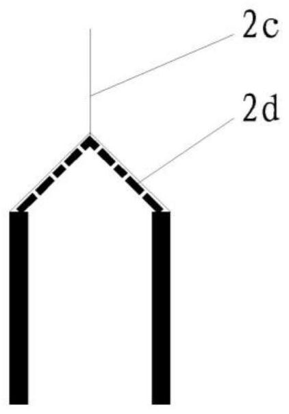
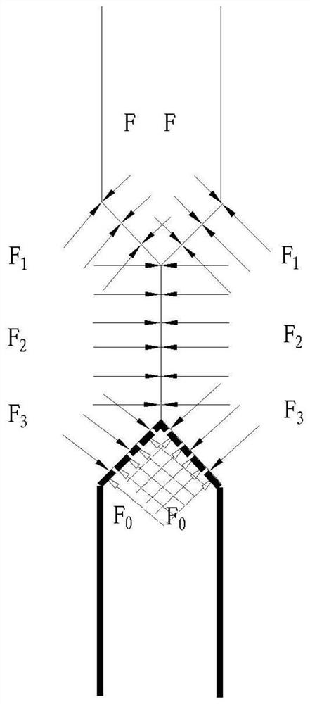
[0023] image 3 Schematic diagram of the force-bearing structure of an elastic thin tube figure 1 ; Figure 4 Schematic diagram of the force-bearing structure of an elastic thin tube figure 2 ; Figure 5 Schematic diagram of the force-bearing structure of an elastic thin tube image 3 ;

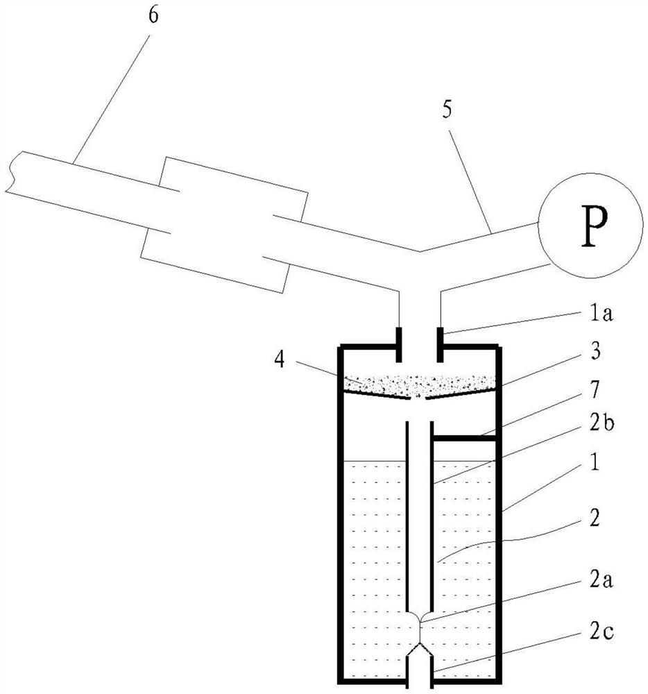
[0024] This embodiment provides a positive pressure pipeline automatic drainage device, which includes a water discharge bucket 1 and a water discharge pipe assembly 2 installed in the water discharge bucket. The upper end of the water discharge pipe assembly is used to receive the water flow in the pressure measuring tube. The lower end of the water discharge pipe assembly is connected to the water outlet of the water discharge bucket, and the middle or bottom section of the water discharge pipe assembly is an elastic thin tube 2a. The middle section is the middle position between the upper end and the lower end of the water discharge pipe assembly, and the bottom section is the lower ...


PUM


Abstract

The invention discloses an automatic drainage device for a positive pressure pipeline. The device comprises a water discharging bucket and a water discharging pipe assembly installed in the water discharging bucket. The upper end of the water discharging pipe assembly is used to receive water flow in a pressure measuring tube. The lower end of the water discharging pipe assembly is connected to awater outlet of the water discharging bucket. The middle or bottom section of the water discharging pipe assembly is an elastic thin tube. The structure of the device can realize the automatic drainage function, and has a simple structure and low cost. The device is suitable for mine air pressure system pipelines and water-bearing coal seam pressure measurement pipelines, can quickly and conveniently remove the water accumulation in the air pressure pipeline, in the pressure measuring tube due to the water content in the coal seam to be measured during the process of measuring the coal seam gas pressure, and in other positive pressure pipelines.

Description

technical field [0001] The invention relates to the technical field of coal mine safety, in particular to an automatic drainage device for a positive pressure pipeline. Background technique [0002] In the underground production process of coal mines, there are problems of water accumulation in positive pressure pipelines that are difficult to discharge, such as water accumulation in medium pressure air pipes of mine pressure air system or water accumulation in gas pressure measurement boreholes; [0003] The mine pressure air system plays an important role in mine safety production, and at the same time provides power for various pneumatic devices and tools in the mine. During the compressed air process, due to the effect of temperature difference, the vaporized water in the compressed air pipeline will condense into liquid water, and the increase in the amount of liquid water will cause the effective section of the partial pipeline in the compressed air pipeline to become ...

Claims


Application Information

Patent Timeline
IPC IPC(8): F16K7/07F16K27/02F16L55/07E21B47/06
CPCF16K7/07F16K27/0236F16L55/07E21B47/06
Inventor 韩恩光吕贵春刘志伟胡杰韩承强冉永进位乐张睿李建功张宪尚
Owner CHINA COAL TECH ENG GRP CHONGQING RES INST
Features
  • R&D
  • Intellectual Property
  • Life Sciences
  • Materials
  • Tech Scout
  • Unparalleled Data Quality
  • Higher Quality Content
  • 60% Fewer Hallucinations
Learn More