Flue gas diversion structure and device, waste heat boiler and flue gas diversion method

The technology of a waste heat boiler and a flow guide device is applied in the field of gas turbine waste heat boilers, which can solve the problems of not significantly improving the uniformity of flue gas flow, reducing the maximum speed of the mouth section, and lengthening the flue.

Pending Publication Date: 2019-10-15
MCC CAPITAL ENGINEERING & RESEARCH
View PDF0 Cites 0 Cited by
  • Summary
  • Abstract
  • Description
  • Claims
  • Application Information

AI Technical Summary

Problems solved by technology

However, doing so will lengthen the flue and increase equipment manufacturing costs. Moreover, the lengthening of the flue duct will also increase the heat dissipation loss of the boiler and reduce the thermal efficiency of the boiler.
[0007] 2. Arrange an inflection point on the upper surface of the flue to adjust the elevation angle of the upper surface of the flue, select a suitable elevation angle, and change the upper surface of the single elevation angle to a front and rear two-stage panel with an elevation angle of 30° and 50° respectively, thereby reducing the mouth section The maximum speed of the flue gas is reduced, and the recirculation zone in the upper part of the flue is reduced, but the uniformity of the final flue gas flow has not been significantly improved
However, deflectors in this area still have shortcomings: compared with other areas, the flue gas flow velocity in the lowermost part of the flue is relatively large, and the fluctuation is relatively large. Due to the vortex impact of the flue, there is a risk of deformation and cracking of the deflector, and part of the flue gas concentrates on the bottom tube bundle; when the air velocity at the inlet of the flue is high, the deflector has to bear a greater impact
This solution cannot be directly applied to the existing operating waste heat boilers, and cannot change the harm caused by the impact of high-speed flue gas on the bottom tube bundle
[0012] These technologies can improve the uniformity of the flow field to a certain extent, but none of them can adjust the flue gas according to the flow and temperature changes of the flue gas exhausted by the gas turbine, and cannot adapt to various working conditions of the gas turbine.

Method used


Image

  • Flue gas diversion structure and device, waste heat boiler and flue gas diversion method
  • Flue gas diversion structure and device, waste heat boiler and flue gas diversion method
  • Flue gas diversion structure and device, waste heat boiler and flue gas diversion method

Examples


Embodiment Construction

[0078] The details of the present invention can be understood more clearly with reference to the accompanying drawings and the description of specific embodiments of the present invention. However, the specific embodiments of the present invention described here are only for the purpose of explaining the present invention, and should not be construed as limiting the present invention in any way. Under the teaching of the present invention, the skilled person can conceive any possible modification based on the present invention, and these should be regarded as belonging to the scope of the present invention.

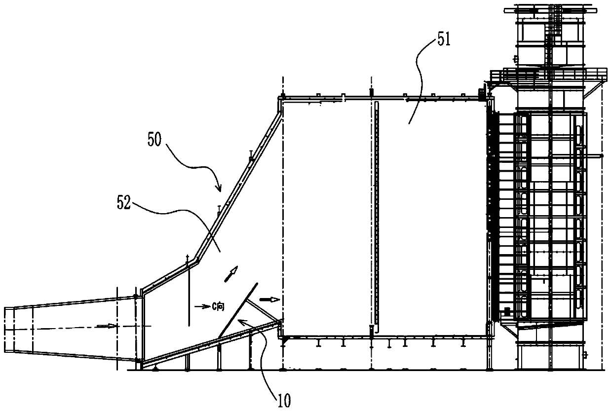
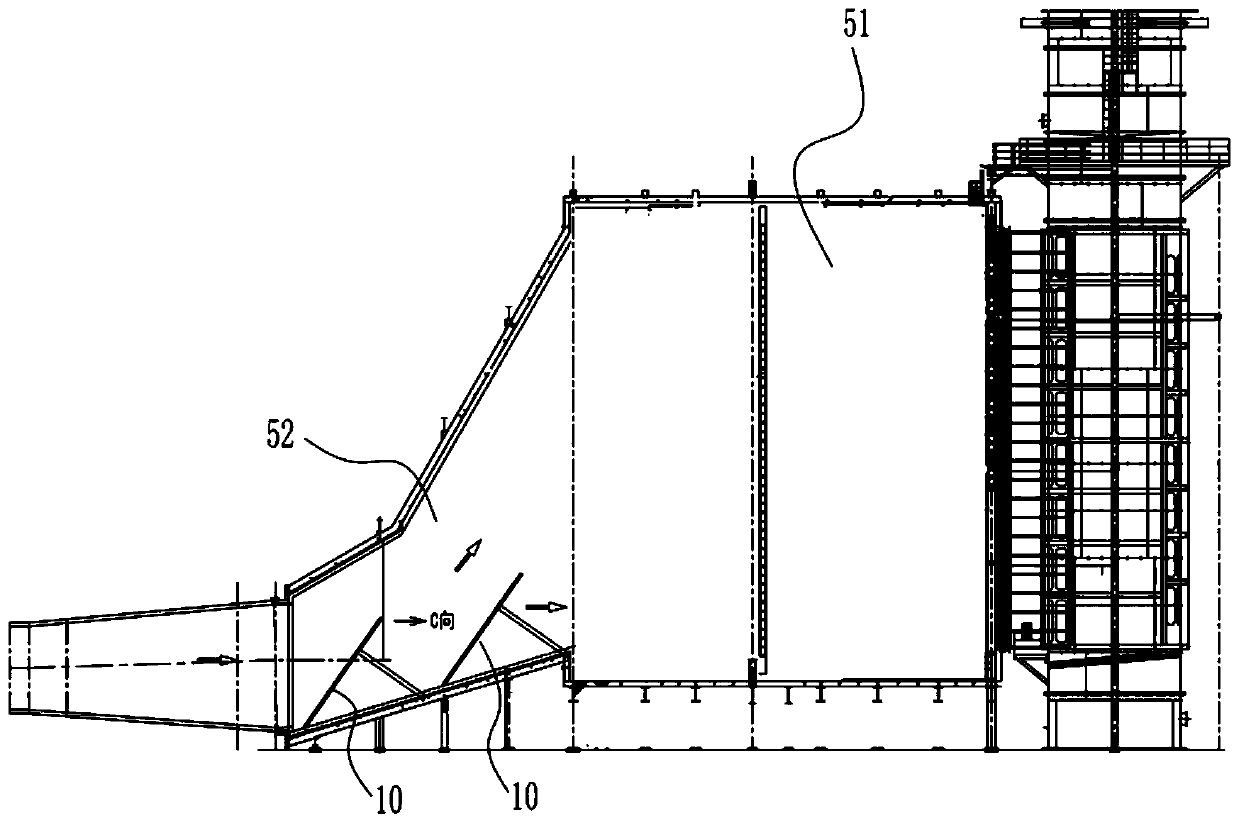
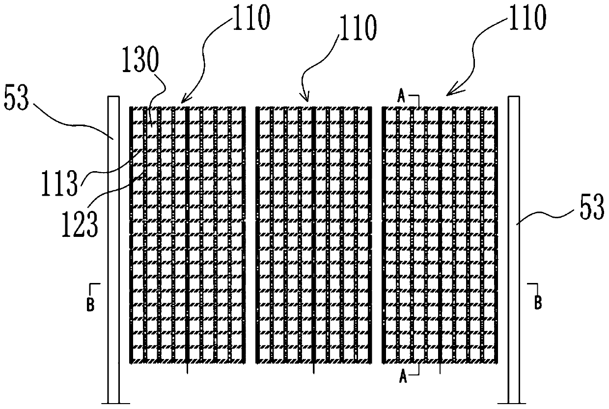
[0079] Such as Figure 1 to Figure 14 As shown, the present invention proposes a flue gas diversion structure 10 for diverting the flue gas in the inlet flue 52 of the waste heat boiler 50. The flue gas diversion structure 10 includes a drive unit 200 and at least one diversion grille unit 100. The guide grill unit 100 has a first grill assembly 110, such as Figure 5 A...


PUM


Abstract

The invention provides a flue gas diversion structure and device, a waste heat boiler and a flue gas diversion method. The flue gas diversion structure comprises a driving unit and at least one diversion grating unit, the diversion grating unit is provided with a first grating assembly, the first grating assembly comprises a first mounting plate and a plurality of first grating plates arranged atpreset intervals, and the first grating plates are rotatably connected to the first mounting plate; and the driving unit comprises a first rotating mechanism, and the first rotating mechanism drives the first grating plates to rotate so as to adjust or maintain an included angle between the first grating plates and the horizontal plane. The flue gas diversion structure and device, the waste heat boiler and the flue gas diversion method provided by the invention can ensure that flue gas can uniformly enter the waste heat boiler under different working conditions.

Description

technical field [0001] The invention relates to the technical field of gas turbine waste heat boilers, in particular to a flue gas diversion structure, a device, a waste heat boiler and a flue gas diversion method for waste heat boilers and other flue gas channels with sudden expansion. Background technique [0002] With the increasingly serious shortage of resources and environmental pollution, energy saving and effective use of waste heat have become the common concern of the world today. The massive development and utilization of natural gas resources has led to the rapid development of high-efficiency, low-pollution gas-steam combined cycle waste heat boiler power generation technology. As one of the three major equipments of the gas-steam combined cycle, the waste heat boiler is located between the gas turbine and the steam turbine. A large number of heat exchangers are arranged to absorb the exhaust heat of the gas turbine and generate high-temperature steam for the st...

Claims


Application Information

Patent Timeline
Patent Type & Authority Applications(China)
IPC IPC(8): F23C9/06F23M9/00
CPCF23C9/06F23M9/003
Inventor 耿明山向继涛王永涛
Owner MCC CAPITAL ENGINEERING & RESEARCH
Why Eureka
Try Eureka