Waste incineration residue treatment furnace

A technology for incinerators and treatment furnaces, which is applied in the directions of incinerators, combustion methods, combustion types, etc., and can solve the problem of incinerators not removing the garbage attached to the inner wall.

Active Publication Date: 2019-10-15
东莞粤丰环保电力有限公司
View PDF7 Cites 0 Cited by
  • Summary
  • Abstract
  • Description
  • Claims
  • Application Information

AI Technical Summary

Problems solved by technology

[0003] In order to solve the above technical problems, the present invention provides a waste incinerator residue treatment furnace to solve the problem that the existing incinerator does not remove the structure of the garbage attached to the inner wall

Method used


Image

  • Waste incineration residue treatment furnace
  • Waste incineration residue treatment furnace
  • Waste incineration residue treatment furnace

Examples


Embodiment

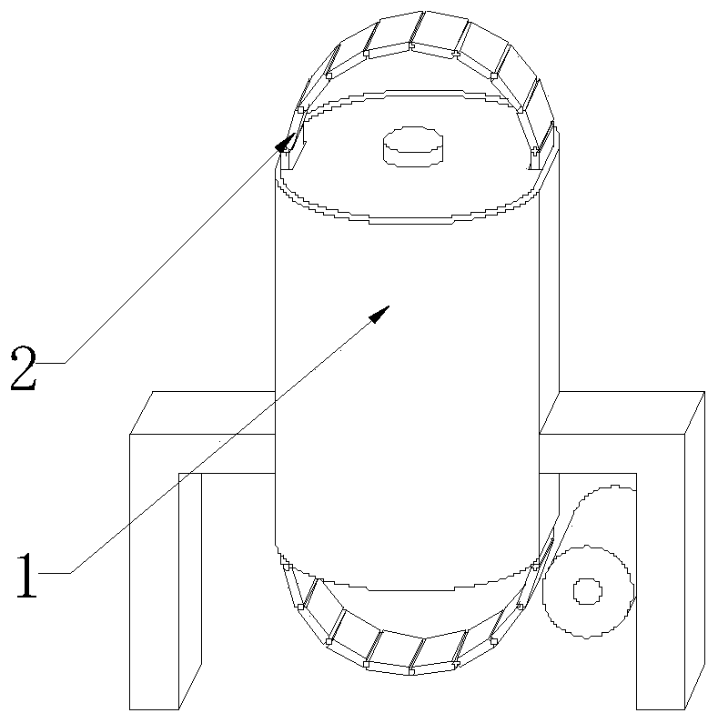
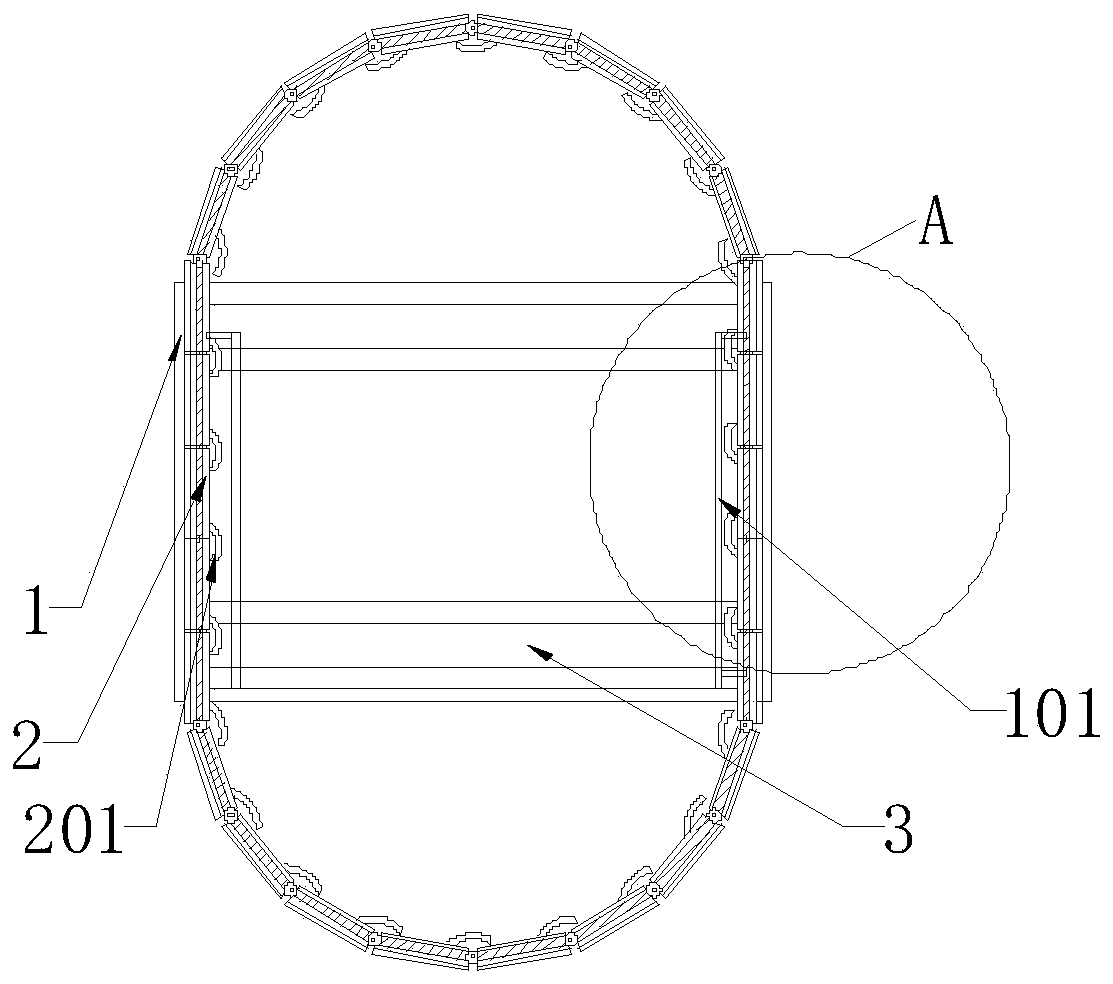
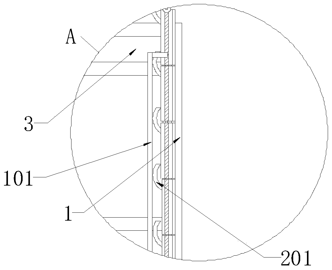
[0027] as attached figure 1 to attach Figure 8 Shown:

[0028] The present invention provides a waste incineration residue treatment furnace, which includes: an incineration cylinder 1, a limit rod 101, a positioning rod 102, a shift roller 103, a wall cleaning belt 2, a limit barb 201, a transposition hole 202, a cleaning Wall belt positioning frame 203, spring buckle 204, contact rod 205, wall clearing ring 3, direction changing block 301 and locking wheel 302; the inside of the incineration cylinder 1 is provided with a limit rod 101, and one side of the limit rod 101 is provided with a positioning rod 102, one side of the limit rod 101 is provided with a displacement roller 103, the inside of the incinerator 1 is provided with a wall cleaning belt 2, one side of the wall cleaning belt 2 is provided with a limit barb 201, and one end of the wall cleaning belt 2 is provided with Transposition hole 202, one side of wall cleaning belt 2 is provided with cleaning belt posit...


PUM


Abstract

The invention provides a waste incineration residue treatment furnace. The waste incineration residue treatment furnace comprises an incineration barrel, a wall cleaning belt and a wall cleaning ring,wherein the wall cleaning belt is arranged inside the incineration barrel, the wall cleaning ring is arranged on one side of the wall cleaning belt, and transposition holes can be blocked through spring buckles, so that the wall cleaning ring stays on the spring buckles, then the wall cleaning ring can be supported on the spring buckles in the upward process, and the inner wall of the wall cleaning ring can be stably cleaned through the spring buckles; when the wall cleaning ring reaches the top end of the incineration barrel, shifting rolling wheels are in contact with racks on the inner walls of the transposition holes to rotate, so that the shifting rolling wheels rotate to drive locking wheels to rotate, then the locking wheels are popped off from the support of abutting rods, and then the wall cleaning ring is separated from the support of the abutting rods; and meanwhile, a directional falling area can be provided for the wall cleaning ring falling down from the top of the incineration barrel through positioning rods and sliding grooves formed in the inner wall of the wall cleaning belt, so that the wall cleaning ring falls from the top end of the incineration barrel to clean the interior of the incineration barrel.

Description

technical field [0001] The invention belongs to the technical field of waste incineration residue treatment structure, and more specifically relates to a waste incineration residue treatment furnace. Background technique [0002] The coking problem of waste incinerators is caused by the adhesion of the inertial transported ash particles on the initial deposition layer. In addition to the properties of the initial layer, it is also related to the temperature of the impacted ash particles. When the temperature of the impacted ash particles is very high, it is molten When it is in a liquid state, it is easy to bond, which intensifies the coking process. The thickness of the ash coke layer is usually uneven, which is related to the structure of the furnace, the middle position of combustion, the aerodynamic characteristics, the temperature characteristics of the furnace and the physical and chemical properties of the fuel. Based on the above description, the garbage attached to ...

Claims


Application Information

Patent Timeline
IPC IPC(8): F23G5/44F23J1/06
CPCF23G5/44F23J1/06F23J2700/003
Inventor 张春喜
Owner 东莞粤丰环保电力有限公司
Why Eureka
Try Eureka