Electromagnetic compatibility testing load device and testing system of new energy automobile electric driving system

An electric drive system, a technology for new energy vehicles, applied in the direction of measuring devices, measuring electricity, measuring electrical variables, etc., can solve the problems of non-adjustable speed, high test cost, high energy consumption, etc., to avoid radiation interference, avoid wall breaking Renovate and realize the effect of recycling

Pending Publication Date: 2019-10-15
深圳市北测标准技术服务有限公司
View PDF0 Cites 17 Cited by
  • Summary
  • Abstract
  • Description
  • Claims
  • Application Information

AI Technical Summary

Problems solved by technology

[0004] The driving motor system needs to simulate the normal working state of the motor during the electromagnetic compatibility test, so the motor is loaded. At present, holes are usually drilled on the side wall of the anechoic chamber, and the load motor outside the anechoic chamber and the motor under test in the anechoic chamber are connected through the transmission shaft. The two are connected, the distance between the two is relatively long, the axes are difficult to align, and the cost of transforming the darkroom is high. In addition, there are reports that a hysteresis motor is used as the load motor, but it has the characteristics of low power and non-adjustable speed, so it is not suitable for high-power For the test of the motor, there are also problems such as high energy consumption and high test cost in the whole test process

Method used


Image

  • Electromagnetic compatibility testing load device and testing system of new energy automobile electric driving system
  • Electromagnetic compatibility testing load device and testing system of new energy automobile electric driving system
  • Electromagnetic compatibility testing load device and testing system of new energy automobile electric driving system

Examples


Embodiment Construction

[0028] The following will clearly and completely describe the technical solutions in the embodiments of the present invention with reference to the accompanying drawings in the embodiments of the present invention. Obviously, the described embodiments are only some, not all, embodiments of the present invention. Based on the embodiments of the present invention, all other embodiments obtained by persons of ordinary skill in the art without making creative efforts belong to the protection scope of the present invention.

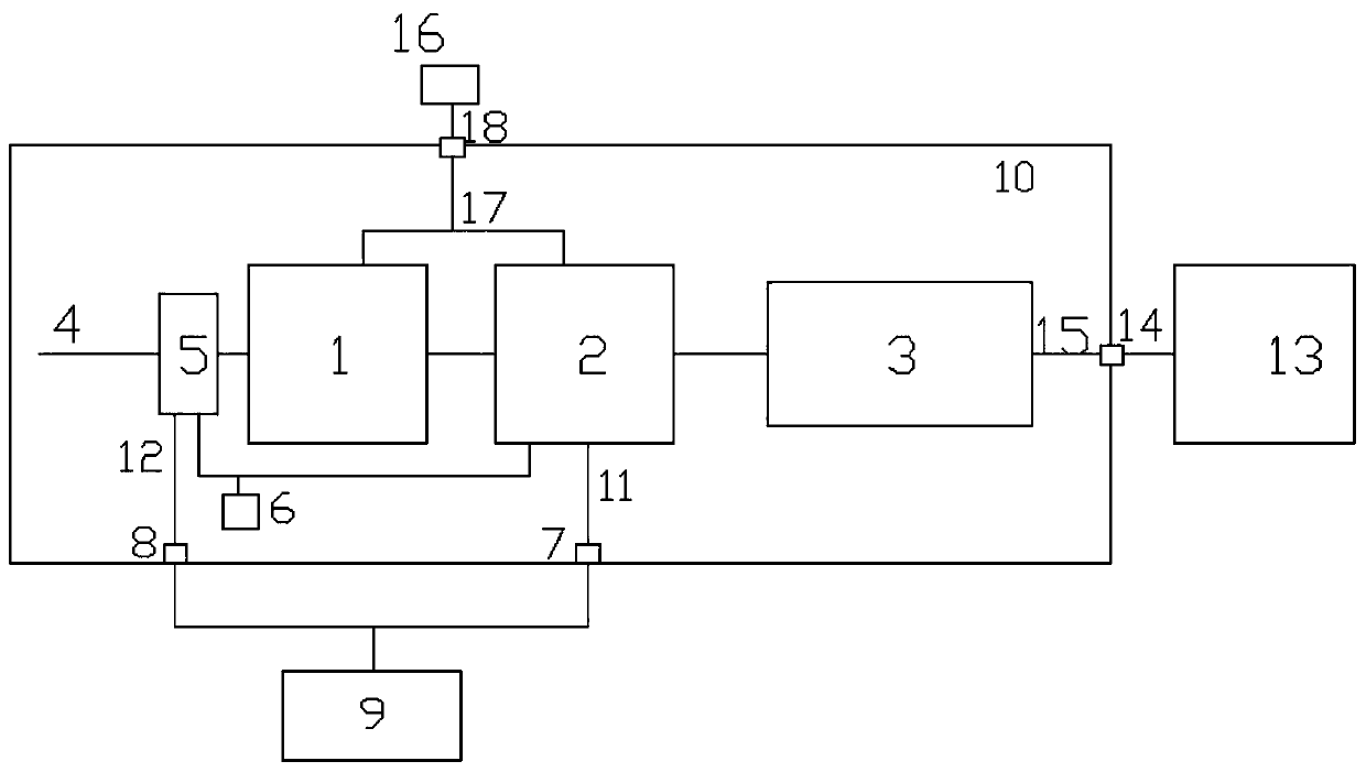
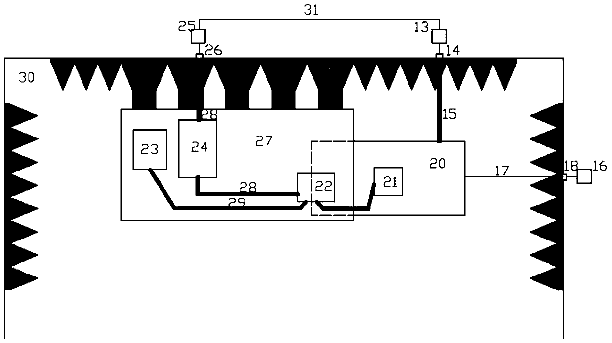
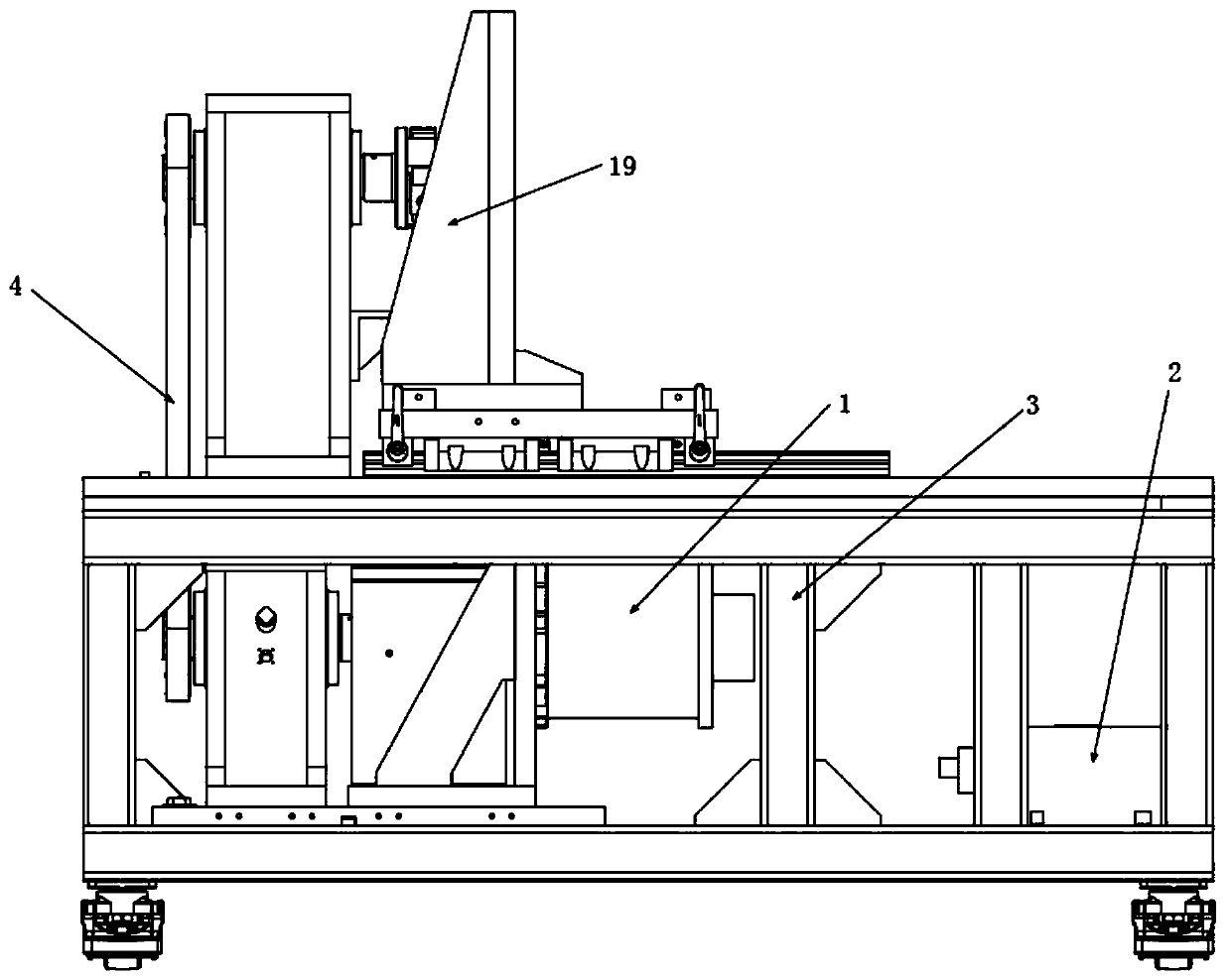
[0029] Refer to attached figure 1 and image 3As shown, a new energy vehicle electric drive system electromagnetic compatibility test load device includes a load motor 1, a load motor controller 2, a DC high voltage filter 3, a transmission device 4, a torque speed sensor 5, A power supply 6 , a first photoelectric signal converter 7 , a second photoelectric signal converter 8 and a monitoring device 9 arranged outside the shielding box 10 . The load motor 1...


PUM


Abstract

The invention discloses an electromagnetic compatibility testing load device and a testing system of a new energy automobile electric driving system. The load device comprises a load motor, a load motor controller, a transmission device, a torque rotating speed sensor, a power supply, a first photoelectric signal converter, a second photoelectric signal converter, a monitoring device, a DC high voltage filter and a screening box; the testing system comprises the load device, an electric driving system, a low-voltage artificial network, a high-voltage artificial network, a high-voltage DC source, a DC filter, a testing table and an anechoic chamber. The load device is movable, capable of realizing high-rotating speed large torque and used for performing electromagnetic compatibility testingof the large power motor, thereby preventing an operation of importing the radiation interference from the external and preventing the load device from producing radiation interference on the external testing environment; furthermore, the testing system takes electricity from the AC power grid, and the mechanical energy of the tested motor is converted into the electric energy through the load device, and then is merged into the AC power grid, thereby realizing the cyclic utilization of the energy and reducing the experimental consumption.

Description

technical field [0001] The invention relates to the technical field of electromagnetic compatibility testing, in particular to an electromagnetic compatibility testing load device and a testing system for an electric drive system of a new energy vehicle. Background technique [0002] As a new energy vehicle, electric drive vehicles are becoming more and more popular in the market. The core technology that distinguishes new energy vehicles from traditional vehicles is "three electrics", namely: electric drive, battery and electronic control. The core component of one of the large electric vehicles, the electric drive system, is a key component that affects the driving safety of the vehicle. It usually uses a high-voltage power supply of several hundred volts, and its working power is much greater than that of the low-voltage components in traditional vehicles. The motor controller Most of the main circuits use high-frequency switching IGBTs to achieve better motor control per...

Claims


Application Information

Patent Timeline
Patent Type & Authority Applications(China)
IPC IPC(8): G01R31/00
CPCG01R31/001
Inventor 谢玉章刘小军莫国延
Owner 深圳市北测标准技术服务有限公司
Why Eureka
Try Eureka