Horizontal spiral discharge sedimentation filtration centrifuge and secondary separation process thereof

A horizontal screw and centrifuge technology, which is applied in the field of centrifuges, can solve problems such as bottlenecks, oil yields that cannot be improved, and drum residue deterioration, etc., to achieve high liquid yields and complete dehydration of secondary fabrics Effect

Pending Publication Date: 2019-10-18
成都高分离心机有限公司
View PDF0 Cites 10 Cited by
  • Summary
  • Abstract
  • Description
  • Claims
  • Application Information

AI Technical Summary

Problems solved by technology

[0003] At the same time, the oil yield of the existing horizontal spiral unloading sedimentation centrifuge used in the hot pot bottom material industry has basically reached the bottleneck, and the oil yield cannot be further improved; in addition, the residue in the drum deteriorates, which affects the problem of the next use increasingly prominent
[0004] Now, by combining the advantages of horizontal screw discharge sedimentation centrifuge and piston pusher centrifuge, a new type of horizontal screw discharge sedimentation filter centrifuge and its secondary separation process are designed, which can perfectly solve the above problems. And there is no similar equipment in the market

Method used


Image

  • Horizontal spiral discharge sedimentation filtration centrifuge and secondary separation process thereof
  • Horizontal spiral discharge sedimentation filtration centrifuge and secondary separation process thereof
  • Horizontal spiral discharge sedimentation filtration centrifuge and secondary separation process thereof

Examples


Embodiment Construction

[0046] The present invention will be further described below in conjunction with the accompanying drawings, but the protection scope of the present invention is not limited to the following description.

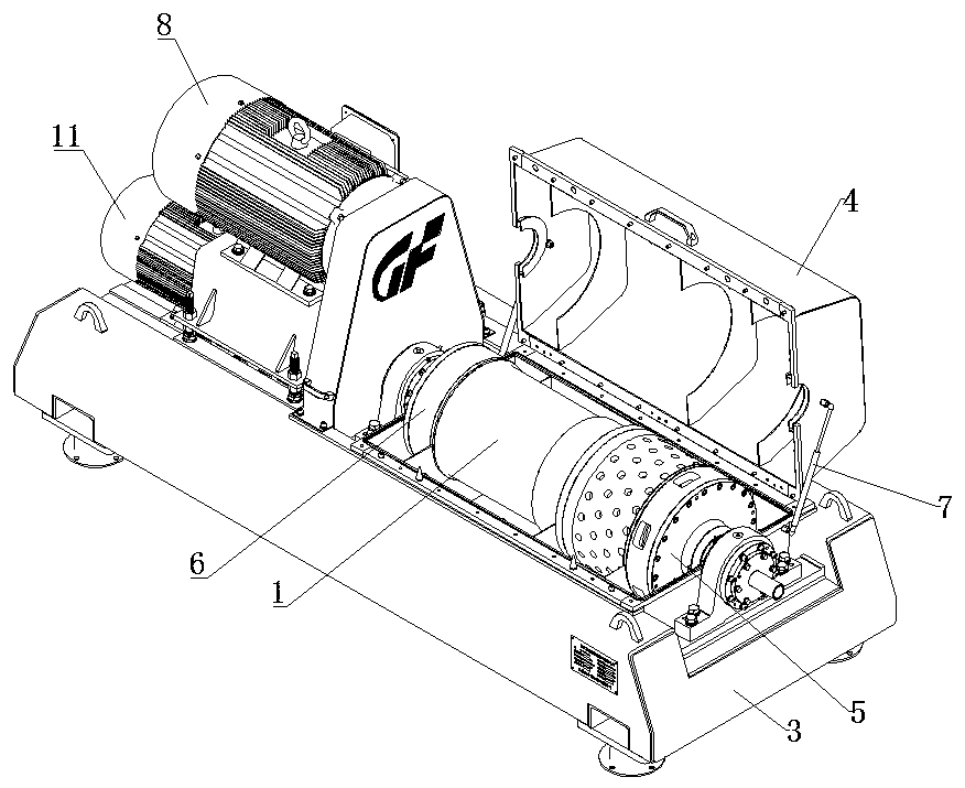
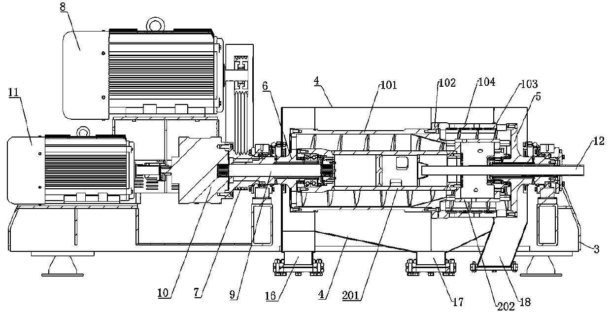
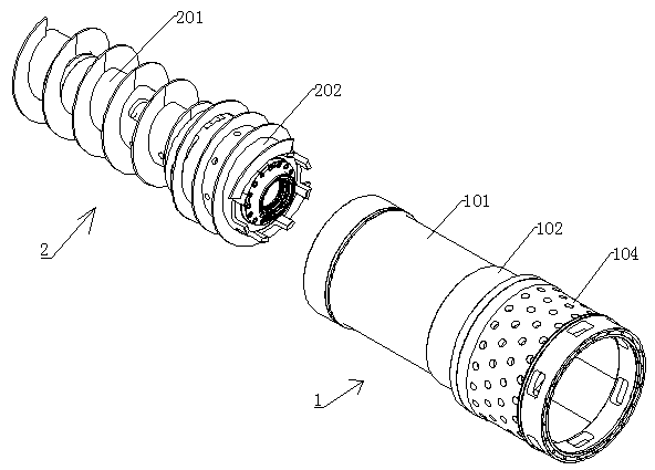
[0047] Such as Figure 1~Figure 10 As shown, a horizontal screw discharge sedimentation filter centrifuge includes a machine base 3 and a casing 4 . The casing 4 is arranged on the machine base 3 , the drum part 1 is arranged in the casing 4 , and the screw pusher 2 is arranged in the drum part 1 .

[0048] In this solution, the casing 4 is divided into two parts, an upper casing and a lower casing, one side of which is hinged and the other side can be opened. The opening and closing of the upper casing and the lower casing is realized through a pneumatic strut 13 . In order to achieve good sealing, a rectangular groove is formed on the end surface of the lower casing at the contact surface of the upper casing and the lower casing, and a rectangular sealing strip 14 is arra...


PUM


Abstract

The invention relates to a horizontal spiral discharge sedimentation filtration centrifuge. The horizontal spiral discharge sedimentation filtration centrifuge comprises a drum part, a spiral materialpusher, a machine base and a cover shell, wherein the cover shell is arranged on the machine base; a drum component is arranged in the cover shell, the drum component is internally provided with thespiral material pusher, and the drum component comprises a straight-section drum, a butt-joint flange drum and a screen drum which are sequentially arranged from left to right; a screen is arranged inthe screen drum, and the butt-joint flange drum is provided with a conical cavity; the spiral material pusher comprises spiral material pusher components I and spiral material pusher components II, and seam allowances of the spiral material pusher components I and the spiral material pusher components II are in fit connection; the spiral material pusher components I are positioned in the straight-section drum and the butt-joint flange drum, and material feeding bins and material feeding holes are formed in the spiral material pusher components I; and the spiral material pusher components II are positioned in the screen drum, and a plurality of through holes are formed in the inner walls of spiral material pusher components II. The invention further discloses a secondary separation processof the horizontal spiral discharge sedimentation filtration centrifuge. The horizontal spiral discharge sedimentation filtration centrifuge has the beneficial effects that the separation effect is improved, the liquid outlet rate is high, the leakproofness is good, and the maintenance cost is low.

Description

technical field [0001] The utility model relates to the technical field of centrifuges, in particular to a horizontal spiral unloading sedimentation filter centrifuge and its secondary separation process. Background technique [0002] Horizontal spiral unloading decanter centrifuge is an automatic equipment widely used in continuous feeding, separation and unloading in chemical, sewage, medical, food and other industries. The working principle of this type of centrifuge is: the drum and the screw rotate at a high speed in the same direction at a certain differential speed, and the material continuously enters the feeding bin of the screw pusher from the feeding pipe, and enters the drum after acceleration. Under the action of centrifugal force, the heavier The solid phase deposits on the drum wall to form a sediment layer. The screw pusher continuously pushes the deposited solid phase to the cone section of the drum, and is discharged out of the machine through the slag dis...

Claims


Application Information

Patent Timeline
Patent Type & Authority Applications(China)
IPC IPC(8): B04B1/20B04B7/16B04B11/02B04B11/06B04B15/06
CPCB04B1/20B04B7/16B04B11/02B04B11/06B04B15/06
Inventor 杨彪刘步实
Owner 成都高分离心机有限公司
Why Eureka
Try Eureka