Dehumidification heat exchange device

A technology of heat exchange device and heat pipe heat exchanger, which is applied in the directions of household heating, household heating, heating methods, etc., can solve the problems of increasing the risk of transformation, and achieve the effect of reducing the risk of transformation.

Active Publication Date: 2019-10-18
沈珂
View PDF6 Cites 3 Cited by
  • Summary
  • Abstract
  • Description
  • Claims
  • Application Information

AI Technical Summary

Problems solved by technology

Therefore, if the existing technology is to be retrofitted with U-shaped heat pipes, the

Method used


Image

  • Dehumidification heat exchange device
  • Dehumidification heat exchange device
  • Dehumidification heat exchange device

Examples


Example Embodiment

[0034] In order to make the objectives, technical solutions and advantages of the present invention clearer, the present invention will be further described in detail below with reference to the accompanying drawings. Obviously, the described embodiment is only one embodiment of the present invention, rather than all the embodiments. Based on the embodiments of the present invention, all other embodiments obtained by those of ordinary skill in the art without creative work shall fall within the protection scope of the present invention.

[0035] The "one embodiment" or "embodiment" referred to herein refers to a specific feature, structure, or characteristic that can be included in at least one implementation of the present invention. In the description of the present invention, it should be understood that the directions or positional relationships indicated by the terms "upper", "lower", "left", "right", "top", "bottom", etc. are based on the drawings shown The orientation or ...


PUM

PropertyMeasurementUnit
Diameteraaaaaaaaaa

Abstract

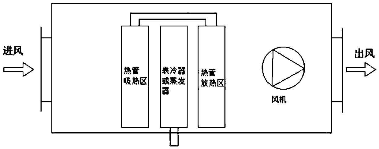
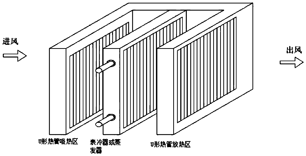
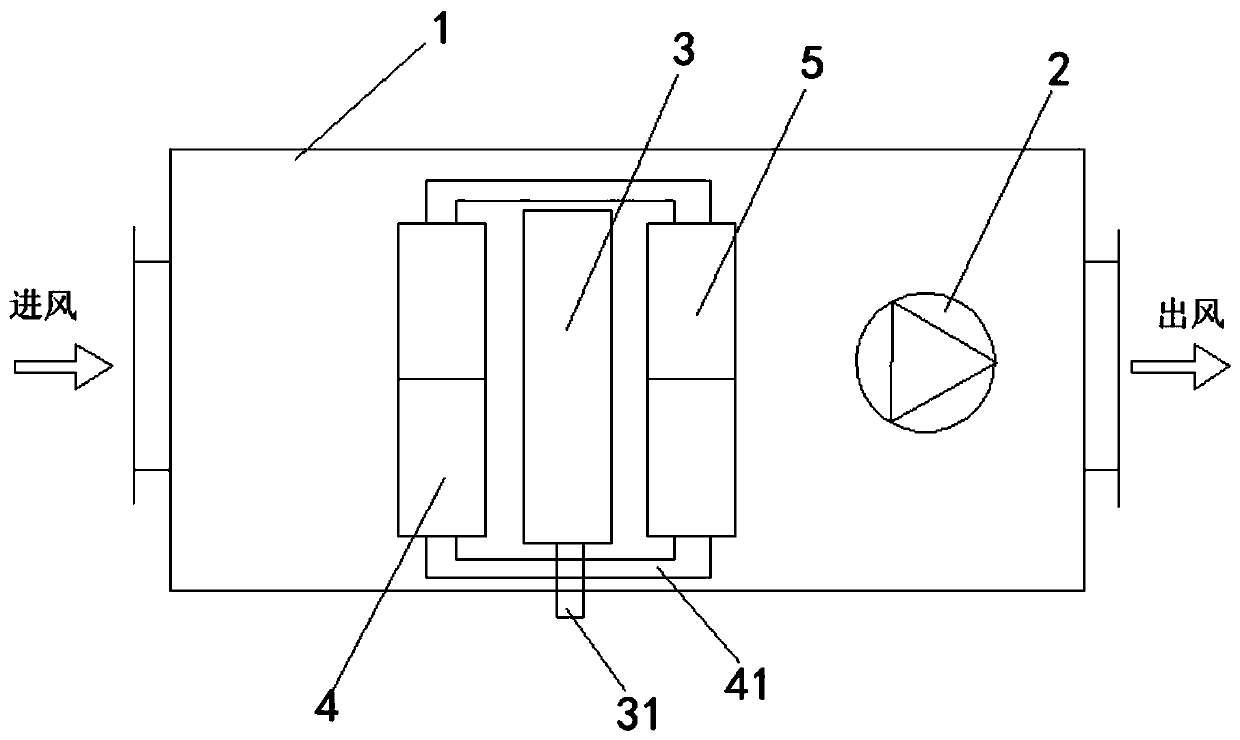
The invention discloses a dehumidification heat exchange device. The dehumidification heat exchange device comprises an air duct, a surface cooler or an evaporator, a first U-shaped heat pipe heat exchanger and a second U-shaped heat pipe heat exchanger, wherein the air duct comprises an air inlet and an air outlet; the surface cooler or the evaporator is arranged in the air duct, the surface cooler or the evaporator (3) is larger than or equal to 600 mm, and an external pipeline is arranged on one side of the surface cooler or the evaporator; the first U-shaped heat pipe heat exchanger is arranged on one side of the external pipeline of the surface cooler or the evaporator, an interval is formed between the first U-shaped heat pipe heat exchanger and the connecting pipeline of a heat insulation area, and the interval is used for being connected with the outside through an external pipeline of the surface cooler or the evaporator; and the second U-shaped heat pipe heat exchanger and the first U-shaped heat pipe heat exchanger are arranged on the other side of the surface cooler or the evaporator in an opposite installation mode, and the pipe diameter of heat exchange pipelines of the first U-shaped heat pipe heat exchanger and the heat exchange pipeline of the second U-shaped heat pipe heat exchanger is 7.0-9.52mm. According to the dehumidification heat exchange device, the structure of the air duct does not need to be changed, so that the transformation risk is reduced, and the modification cost and period are shortened.

Description

technical field [0001] The invention relates to the technical field of dehumidification and drying, in particular to a dehumidification heat exchange device. Background technique [0002] In the field of central air conditioning, constant temperature and humidity air conditioning units are widely used in electronics, machine tools, textiles, medicine and other fields. During operation, the incoming air needs to be cooled and dehumidified first, and then reheated to achieve the required air supply temperature and humidity. Conventional constant temperature and humidity air conditioning units generally use electricity or steam for reheating, which consumes a lot of energy. To reduce energy consumption, heat pipe technology can be used to pre-cool and reheat the air. [0003] Such as Chinese patent CN204026892U. Among them, the Chinese patent uses a U-shaped heat pipe, the pre-cooling pipe of the U-shaped heat pipe on the air inlet side, the evaporator or surface cooler for c...

Claims


Application Information

Patent Timeline
IPC IPC(8): F24F3/14F24F13/30
CPCF24F3/1405F24F13/30
Inventor 沈珂
Owner 沈珂
Why Eureka
Try Eureka