Solid-state annular three-dimensional imaging device

A three-dimensional imaging, ring-shaped technology, applied in measuring devices, optical devices, instruments, etc., can solve problems such as unfavorable device wiring, unfavorable device high-precision measurement, unfavorable camera formation and other problems, and achieves easy calibration, simple structure, and system size. small effect

Pending Publication Date: 2019-10-18
深圳慎始科技有限公司
View PDF0 Cites 1 Cited by
  • Summary
  • Abstract
  • Description
  • Claims
  • Application Information

AI Technical Summary

Problems solved by technology

[0004] Existing devices for large-angle or 360° three-dimensional measurement, the receiving module and the transmitting module are located in the middle of the device, which is not conducive to the wiring of the device, and the short distance between the two mirrors is not conducive to high-precision measurement of the device, and is not conducive to the camera. form a clear image

Method used


Image

  • Solid-state annular three-dimensional imaging device
  • Solid-state annular three-dimensional imaging device
  • Solid-state annular three-dimensional imaging device

Examples


Embodiment 2

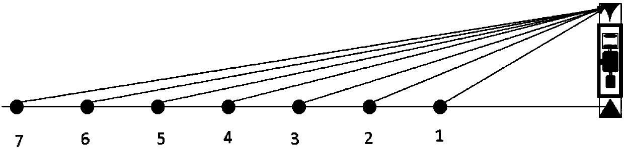
[0042] Such as Figure 5As shown, the difference between the second embodiment and the first embodiment is that the inverted cone reflection module 3 and the area light receiving module 4 in the first embodiment are replaced by a panoramic camera camera module 7 coaxial with the axis of the light emitting module 1, Other structural features of the second embodiment are the same as those of the first embodiment, and will not be repeated here.

Embodiment 3

[0044] Such as Image 6 As shown, the difference between the third embodiment and the first embodiment is that the inverted cone reflection module 3 and the area light receiving module 4 in the first embodiment are replaced by an ultra-wide-angle camera module that is coaxial or perpendicular to the axis of the light emitting module 1 8. Other structural features of the third embodiment are the same as those of the first embodiment, and will not be repeated here.

Embodiment 4

[0046] Such as Figure 7 As shown, the difference between the fourth embodiment and the first embodiment is that the inverted cone reflection module 3 and the area light receiving module 4 in the first embodiment are replaced by a wide-angle camera module 9 perpendicular to the axis of the light emitting module 1 . Other structural features of the fourth embodiment are the same as those of the first embodiment, and will not be repeated here.

[0047] The invention can realize ring-shaped three-dimensional imaging, and does not need a motor to drive parts to rotate, has a solid structure completely, and has the characteristics of simple structure, easy calibration and high service life.


PUM


Abstract

The invention, which belongs to the technical field of photoelectricity, in particular relates to a solid-state annular three-dimensional imaging device comprising a frame supporting module, a light emitting module and an electronic circuit module. The light emitting module and the electronic circuit module are arranged in the frame supporting module. The electronic circuit module is configured tocontrol the light emitting module to emit light. A light cone reflection module that is used for converting light into annular structural light and reflecting the light to a surrounding target area is arranged at one end of the frame supporting module; and an array light receiving module and an inverted cone reflection module that are arranged at the inner side and the outer side of the frame supporting module are arranged at the other end of the frame supporting module, or a camera module is arranged at the other end of the frame supporting module. The inverted cone reflection module is usedfor reflecting reflected light of an object in the target area to the array light receiving module; and the array light receiving module is used for receiving reflected light reflected by the inverted cone reflection module and converting the light into a photoelectric signal for outputting. Compared with the conventional single-point scanning structure, the solid-state annular three-dimensionalimaging device has characteristics of simple structure, small size, and long service life.

Description

technical field [0001] The invention belongs to the field of optoelectronic technology, in particular to a solid-state annular three-dimensional imaging device. Background technique [0002] Traditional image technology mostly refers to two-dimensional plane images, and a single image does not have depth information. With the development of technology, more and more application scenarios hope to obtain three-dimensional information. The main implementation schemes include: binocular vision scheme, infrared structured light combined with camera scheme, pulsed laser scanning combined with camera scheme, etc. [0003] The binocular vision solution requires a lot of calculations to achieve the matching of feature points in the image processing process, and when the distance is long, the binoculars cannot achieve three-dimensional construction; the infrared structured light combined with the camera solution is suitable for close-range three-dimensional construction; pulse The la...

Claims


Application Information

Patent Timeline
Patent Type & Authority Applications(China)
IPC IPC(8): G01B11/00G01B11/02G01C3/00
CPCG01B11/00G01B11/02G01C3/00
Inventor 冷雨泉马维斯占志鹏任利学
Owner 深圳慎始科技有限公司
Why Eureka
Try Eureka