
Display device and backlight module

A technology for backlight modules and display devices, applied in the directions of light guides, optics, optical components, etc., can solve problems such as increasing the thickness of modules

Active Publication Date: 2019-10-18
AU OPTRONICS CORP
View PDF6 Cites 0 Cited by
  • Summary
  • Abstract
  • Description
  • Claims
  • Application Information

AI Technical Summary

Problems solved by technology

However, this method often increases the thickness of the module, or requires a large number of light sources to be designed, so there is room for improvement

Method used


Image

  • Display device and backlight module
  • Display device and backlight module
  • Display device and backlight module

Examples


Embodiment Construction

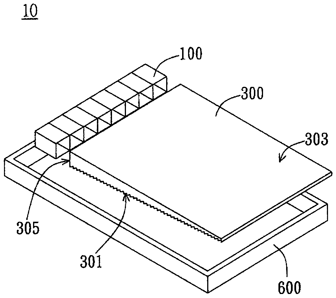
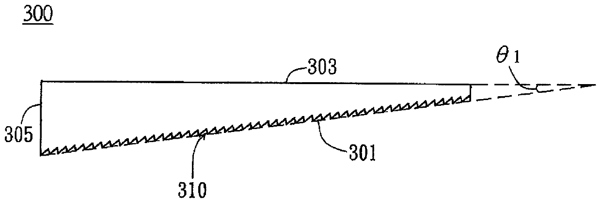
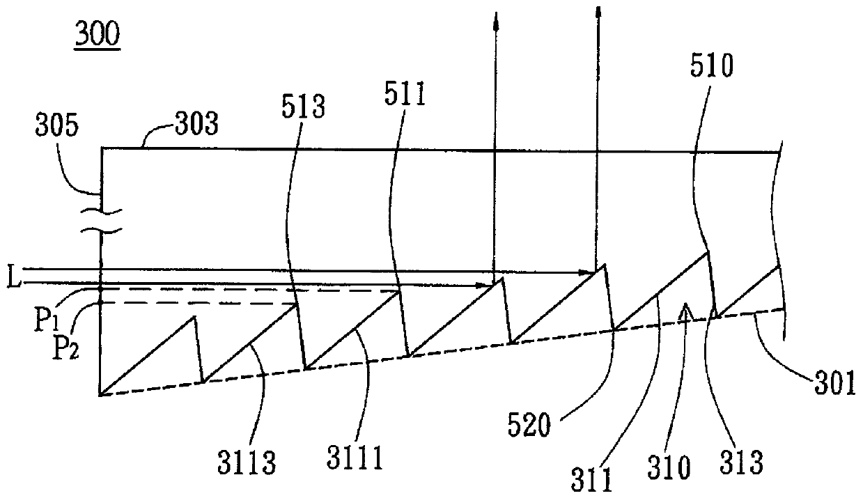
[0049] The implementation of the connection assembly disclosed in the present invention will be described below through specific specific embodiments and accompanying drawings. Those skilled in the art can understand the advantages and effects of the present invention from the content disclosed in this specification. However, the content disclosed below is not intended to limit the protection scope of the present invention. Those skilled in the art can implement the present invention in other different embodiments based on different viewpoints and applications without departing from the spirit of the present invention. In the drawings, the thickness of layers, films, panels, regions, etc., are exaggerated for clarity. Throughout the specification, the same reference numerals denote the same elements. It will be understood that when an element such as a layer, film, region, or substrate is referred to as being "on" or "connected to" another element, it can be directly on or con...


PUM


Abstract

The invention provides a display device and a backlight module using the same. The backlight module comprises a collimated light source and a light guide plate. The light guide plate is provided witha bottom surface and a top surface which are opposite to each other, and light incident surfaces which are respectively connected to the end parts of the bottom surface and the top surface to receivecollimated light from the collimated light source. The bottom surface inclines from the end portion connected with the light incident surface to the top surface. The bottom surface is provided with aplurality of first grooves which are arranged side by side and extend along the light incident surface. The first groove is provided with a first light receiving surface which is provided with a firstend facing the top surface and obliquely extending away from the light incident surface. Compared with the first light receiving surface closer to the light incident surface, the first end of the first light receiving surface farther away from the light incident surface is closer to the top surface at the vertical projection position of the light incident surface.

Description

technical field [0001] The present invention relates to a backlight module and a display device using the same; specifically, the present invention relates to a backlight module capable of providing collimated backlight and a display device using the same. Background technique [0002] Flat and curved display devices have been widely used in various electronic devices, such as mobile phones, personal wearable devices, televisions, vehicle hosts, personal computers, digital cameras, handheld video games, and so on. However, with the continuous improvement of specifications such as resolution, narrow bezel, and thinning, the optical design in the display device is also tested. [0003] Taking a liquid crystal display device as an example, its optical performance is usually closely related to the backlight module disposed behind the display panel. In some designs, it is necessary to use a more collimated backlight to cooperate with the front display panel to achieve the expect...

Claims


Application Information

Patent Timeline
Patent Type & Authority Applications(China)
IPC IPC(8): G02B6/00
CPCG02B6/0016G02B6/0046G02B6/0068G02B6/0086G02B6/003G02B6/0038G02B6/0048G02B6/0036G02B6/0061G02B6/0088
Inventor 曾世福陈嘉鸿施凯腾
Owner AU OPTRONICS CORP
Learn More