Auxiliary fixing mechanism for digital tube display assembly and using method thereof

A fixing mechanism and display technology, which is applied in the direction of assembling printed circuits, instruments, identification devices, etc. of electrical components, can solve the problems of poor flexibility and reduce the number of debugging, so as to increase flexibility, reduce the number of debugging, and improve flexibility. Effect

Active Publication Date: 2021-03-30
ANHUI MINGYANG ELECTRONICS
View PDF6 Cites 0 Cited by
  • Summary
  • Abstract
  • Description
  • Claims
  • Application Information

AI Technical Summary

Problems solved by technology

[0005] In order to overcome the technical problem of poor flexibility of the auxiliary fixing mechanism for digital tube display assembly, the object of the present invention is to provide an auxiliary fixing mechanism for digital tube display assembly and its use method. Complete the fixation between the swing arm and the side swing arm, so that the side swing arm can be rotated at multiple angles, increasing the flexibility of the auxiliary fixing mechanism, and at the same time using the snap ring of the limit sleeve bolt, it can be completed on the side swing arm After the angle is adjusted, the angle is locked to reduce the number of times of debugging, so that the side swing arm has an angle locking structure. By setting the telescopic hanging rod, multiple sets of fixing caps can be installed on the auxiliary fixing mechanism at the same time, so that it can be At the same time, the fixing operation of multiple sets of digital tubes can be completed, and the distance between the two sets of digital tubes can be adjusted with the help of the telescopic rod, thereby effectively improving the processing efficiency of the auxiliary fixing mechanism.

Method used


Image

  • Auxiliary fixing mechanism for digital tube display assembly and using method thereof
  • Auxiliary fixing mechanism for digital tube display assembly and using method thereof
  • Auxiliary fixing mechanism for digital tube display assembly and using method thereof

Examples


Embodiment Construction

[0029] The technical solutions in the embodiments of the present invention will be clearly and completely described below in conjunction with the embodiments of the present invention. Apparently, the described embodiments are only some of the embodiments of the present invention, not all of them. Based on the embodiments of the present invention, all other embodiments obtained by persons of ordinary skill in the art without creative efforts fall within the protection scope of the present invention.

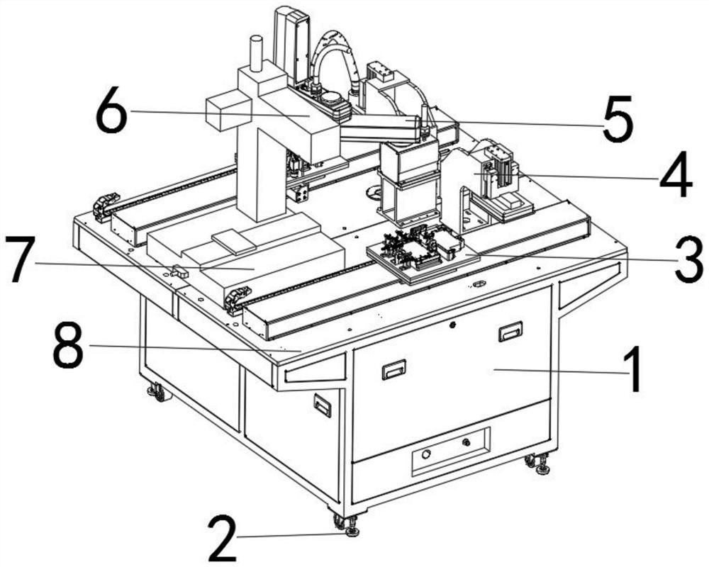
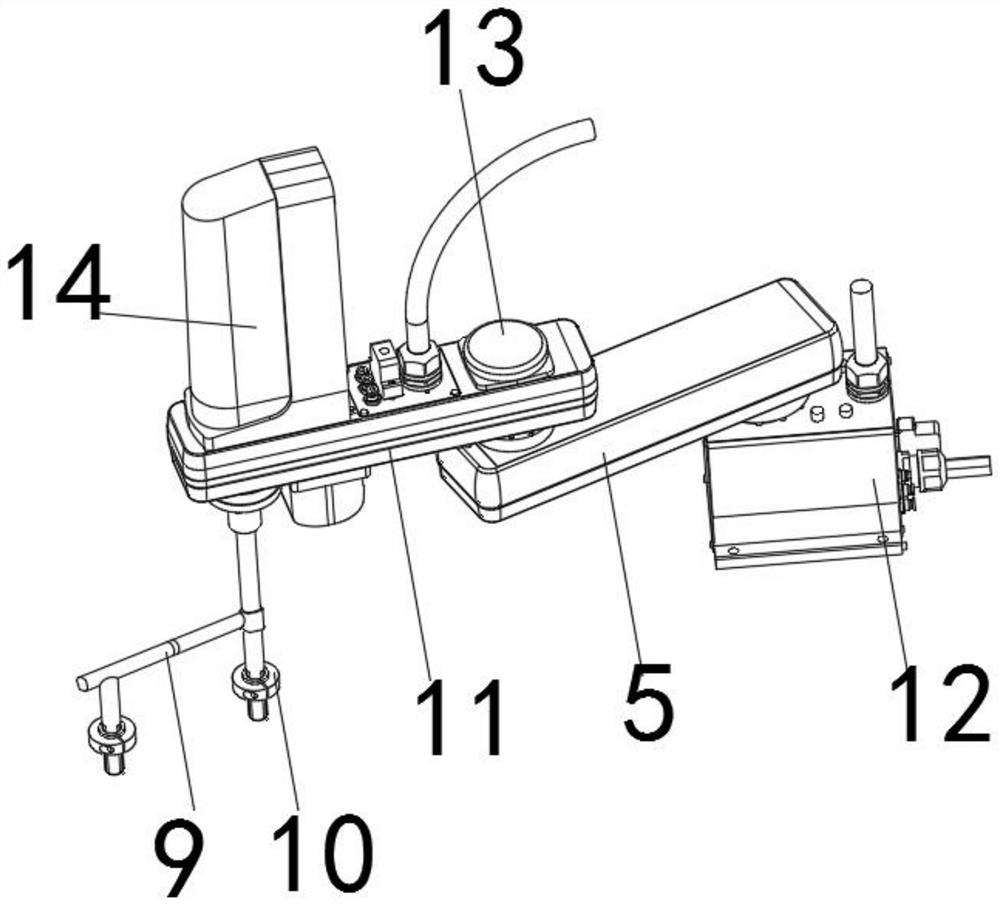
[0030] Such as Figure 1-5As shown, an auxiliary fixing mechanism for the assembly of a digital tube display includes an operating table 8, a rotating arm 5, a telescopic hanging rod 9 and a combination plate 3. The rotating arm 5 is movably installed on the upper outer surface of the operating table 8, and the rotating arm 5 and The operating tables 8 are docked and fixed by the drive base 12, and the upper part of the rotating arm 5 is movably installed with a side swing arm 11,...


PUM


Abstract

The invention discloses an auxiliary fixing mechanism for assembling nixie tube displays. The auxiliary fixing mechanism comprises an operating table, a rotating arm, a telescopic hanging rod and a combined plate; the rotating arm is movably mounted on the outer surface of the upper end of an operating table; the rotating arm is connected and fixed to the operating table through a driving machinebase; a side rotating arm is movably mounted at the upper part of the rotating arm; the rotating arm and the side rotating arm are connected and fixed through a limiting sleeve bolt; the middle of theouter surface of the limiting sleeve bolt is movably sleeved with two groups of clamping tooth rings; the two groups of clamping tooth rings are connected and fixed through clamping grooves; and fastening rings are fixedly connected to the two sides, close to the clamping tooth rings, of the outer surface of the limiting sleeve bolt in a sleeving mode. According to the auxiliary fixing mechanismfor assembling the nixie tube displays, the auxiliary fixing mechanism has a multi-angle rotating structure, so that the flexibility of the auxiliary fixing mechanism is improved, the assembling operation of the multiple groups of nixie tube displays can be completed at the same time, the working efficiency is improved, and the assembling is firmer.

Description

technical field [0001] The invention belongs to the technical field of digital tube display processing, and in particular relates to an auxiliary fixing mechanism, more specifically an auxiliary fixing mechanism for assembling a digital tube display and a use method thereof. Background technique [0002] The auxiliary fixing mechanism for digital tube display assembly is a kind of fixing device for auxiliary fixing operation of the digital tube parts during the assembly process of the digital tube display. The auxiliary fixing mechanism can be used to fix the digital tube parts through the pre-set installation steps. Fixing, by moving each fixing component of the auxiliary fixing mechanism, the assembly operation of the digital tube display can be completed according to the preset order; [0003] The document CN201721181518.5 discloses a processing and fixing tool for digital tubes, including a base on which two clamping plates arranged in parallel are vertically arranged, a...

Claims


Application Information

Patent Timeline
Patent Type & Authority Patents(China)
IPC IPC(8): G09F9/33H05K3/30H05K13/04
CPCG09F9/33H05K3/30H05K13/04
Inventor 陈敏顾亚英邓肖肖
Owner ANHUI MINGYANG ELECTRONICS
Why Eureka
Try Eureka