IC side light-emitting LED with internal drive

A side-emitting and light-emitting chip technology, applied in electrical components, circuits, semiconductor devices, etc., can solve the problems of limited signal transmission, high cost, poor heat dissipation, etc., to solve the problem of limited space, stable and reliable application, and avoid solder fillets. overheating effect

Pending Publication Date: 2019-10-18
SUZHOU YOUYUE ELECTRONICS CO LTD
View PDF0 Cites 0 Cited by
  • Summary
  • Abstract
  • Description
  • Claims
  • Application Information

AI Technical Summary

Problems solved by technology

In the prior art, most LED light-emitting products have the disadvantages of occupying space, limited signal transmission and high cost, which is not conducive to the development of miniaturization and thinning of existing products. Stable for long-term use

Method used


Image

  • IC side light-emitting LED with internal drive
  • IC side light-emitting LED with internal drive
  • IC side light-emitting LED with internal drive

Examples


Embodiment Construction

[0023] The preferred embodiments of the present invention will be described in detail below in conjunction with the accompanying drawings, so that the advantages and features of the present invention can be more easily understood by those skilled in the art, so as to define the protection scope of the present invention more clearly.

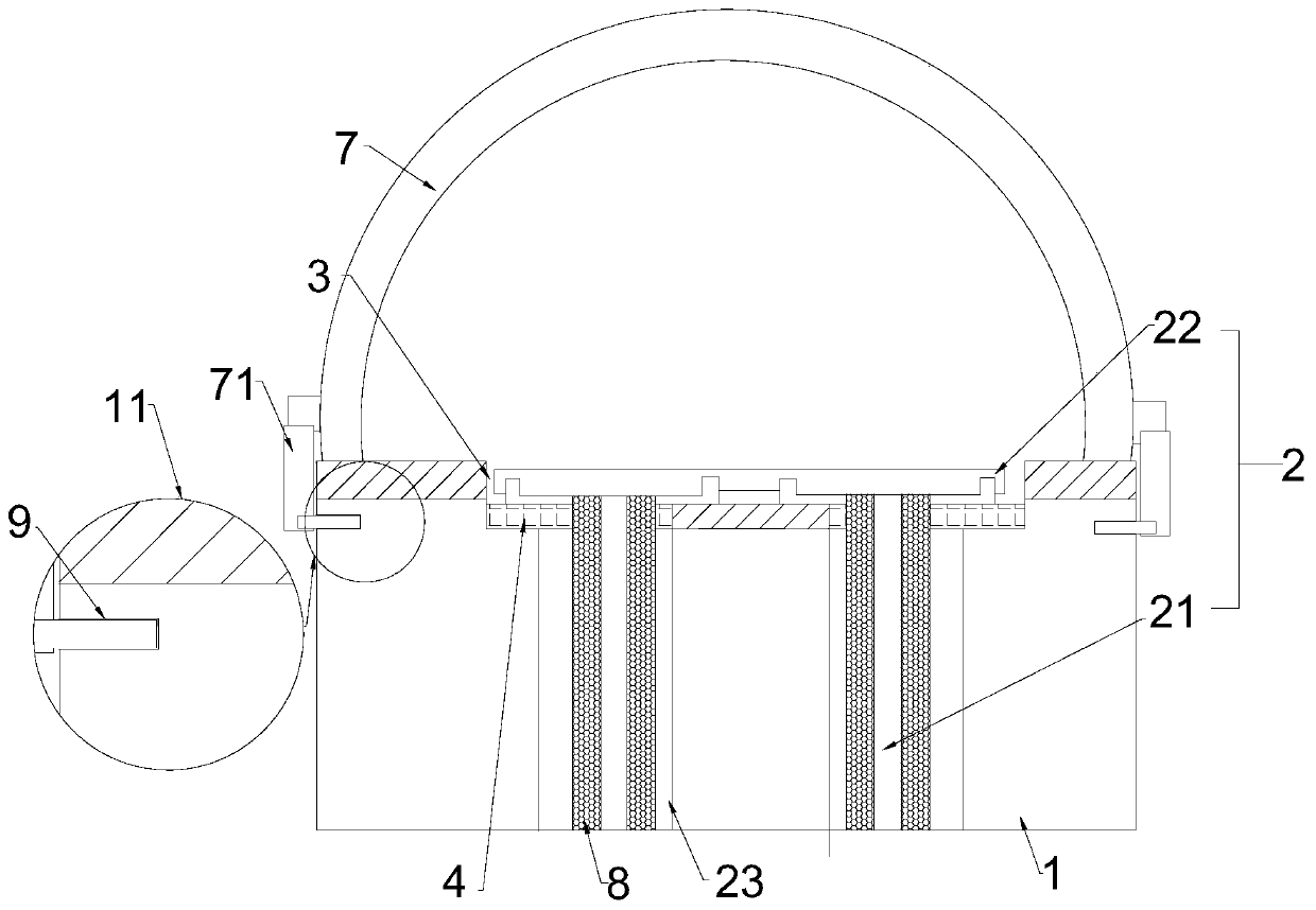
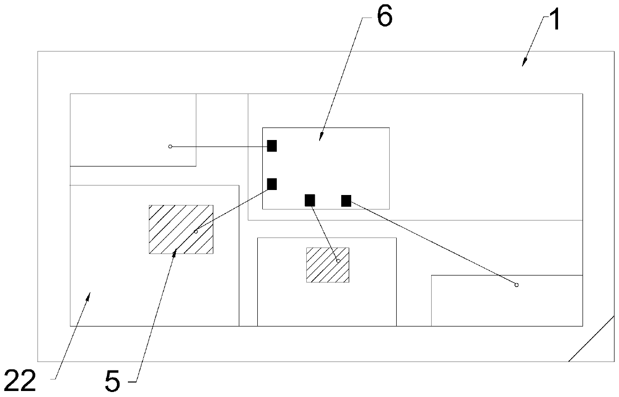
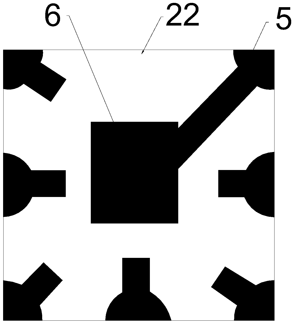
[0024] See attached Figure 1-8 As shown, a side-emitting LED with an internal drive IC includes an insulating body 1, and a plurality of conductive terminals 2 are embedded in the insulating body 1. The conductive terminals 2 have integrally formed welding feet 21 and pads 22. The surface is sunken inward to form a reflective cup 3, and the pads 22 can be exposed on the bottom surface of the reflective cup 3. The LED light-emitting chip 5 and the internal drive IC6 are respectively welded and fixed on the multiple pads 22, and the LED light-emitting chip 5 and the internal drive IC6 can pass through Epoxy resin encapsulation glue is hermetically...


PUM


Abstract

The invention discloses a side light-emitting LED with an internal drive IC. The LED comprises an insulating main body, and a plurality of conductive terminals are embedded in the insulating main body, wherein each conductive terminal is provided with a welding pin and a bonding pad which are integrally formed. The upper surface of the insulating main body is recessed inwards to form a reflectioncup, and the bonding pads can be exposed out of the bottom surface of the reflection cup; an LED light-emitting chip and an internal drive IC are respectively welded and fixed on each of the pluralityof bonding pads; the LED light-emitting chips and the inner drives IC are both located in the reflection cup. The LED light-emitting chips, the internal drives IC and the weld legs are electrically connected through conductive wires. One ends of the welding pins away from the bonding pads are located at the insulating body bottom. A light-transmitting cover is clamped on the insulating main body,and the LED light-emitting chip and the internal drive IC are both located in the light-transmitting cover. A plurality of welding foot supports are arranged in the insulating main body, the weldingfeet and the welding foot supports are equal in number and are in one-to-one correspondence, the welding feet are located in the welding foot supports, heat dissipation materials are filled between the welding feet and the welding foot supports, the structure of the device is simple, the IC chip and the LED light-emitting chips are integrated and driven, and the application stability can be improved.

Description

technical field [0001] The invention relates to the technical field of LEDs, in particular to a side-emitting LED with an internal drive IC. Background technique [0002] Light-emitting diodes (LEDs or LEDS) are solid-state devices that convert electrical energy into light energy. At this stage, under the circumstances of the global pursuit of health, environmental protection pressure, and energy crisis, light-emitting diodes have been recognized as a healthy, energy-saving and environmentally friendly product in the world. An important way is expanding its scope of application at a faster rate. In the prior art, most LED light-emitting products have the disadvantages of occupying space, limited signal transmission and high cost, which is not conducive to the development of miniaturization and thinning of existing products. Stable in case of long-term use. Contents of the invention [0003] In order to overcome the above disadvantages, the object of the present invention...

Claims


Application Information

Patent Timeline
Patent Type & Authority Applications(China)
IPC IPC(8): H01L33/48H01L33/60H01L33/62H01L33/64
CPCH01L33/48H01L33/60H01L33/62H01L33/64H01L33/641
Inventor 王友平
Owner SUZHOU YOUYUE ELECTRONICS CO LTD
Why Eureka
Try Eureka