An improved bag filter

A bag filter and an improved technology are applied in chemical instruments and methods, separation methods, dispersed particle separation and other directions, which can solve the problems of reduced air filtration efficiency, insufficient convenience, energy saving and environmental protection, etc., and achieve the effect of improving the effect.

Active Publication Date: 2021-06-29
山东巨佳生物科技有限公司
View PDF0 Cites 0 Cited by
  • Summary
  • Abstract
  • Description
  • Claims
  • Application Information

AI Technical Summary

Problems solved by technology

[0003] With the increase of the surface area of ​​the filter bag, the air filtration resistance of the filter bag increases and the efficiency of the filter air decreases. The existing one generally uses an external high-pressure air injection pipe to blow off the ash accumulation inside the filter bag, which is not convenient enough, and it is not energy-saving and environmentally friendly.

Method used


Image

  • An improved bag filter
  • An improved bag filter
  • An improved bag filter

Examples


Embodiment 1

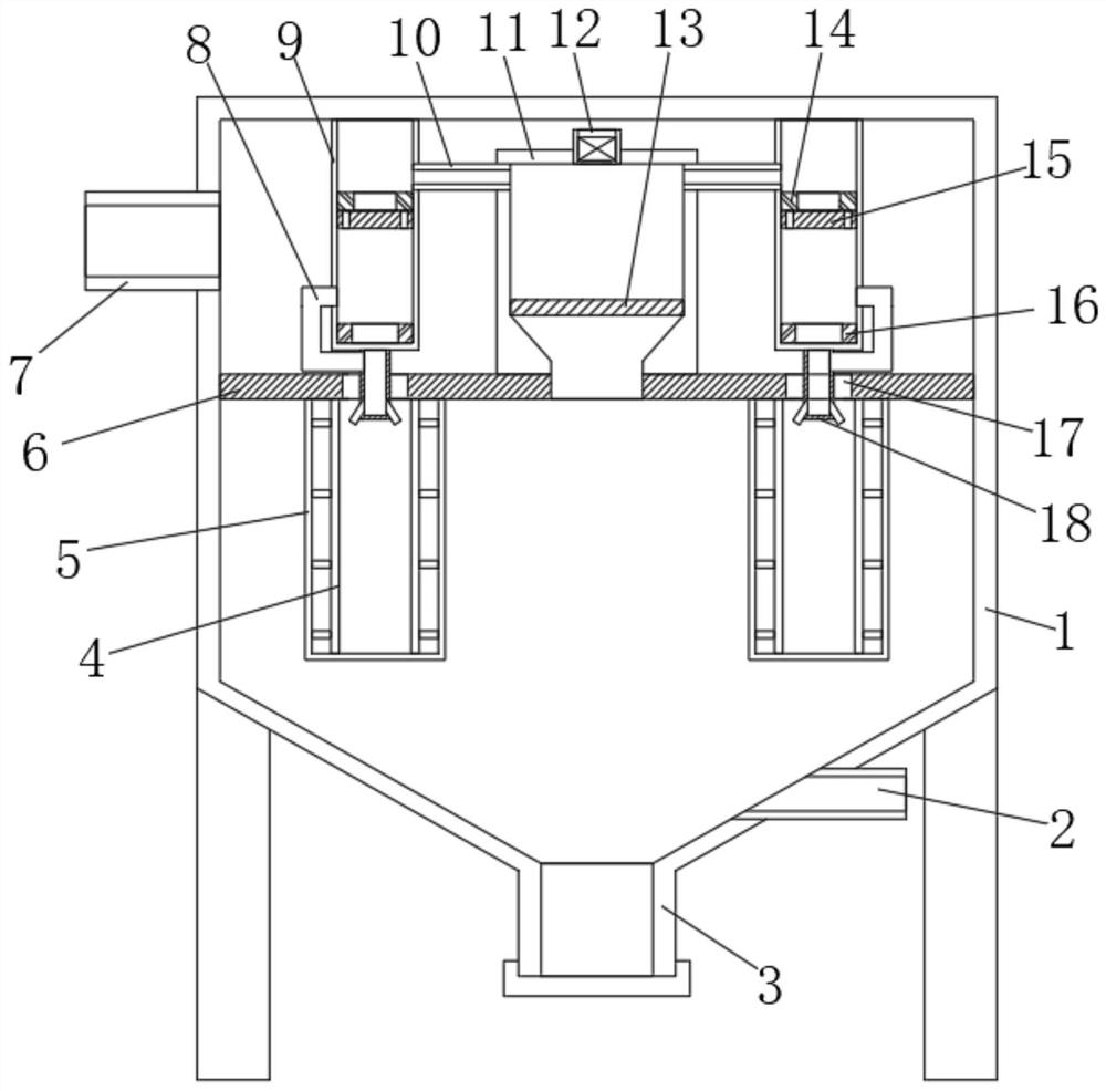
[0021] refer to figure 1 , an improved bag filter, including a housing 1 and an air inlet 2 and an air outlet 7 connected to the housing 1. The lower end of the housing 1 is provided with an ash hopper 3, and the inside of the housing 1 is fixedly connected with a horizontal The partition 6 is provided, and the partition 6 divides the interior of the housing 1 into an air outlet chamber and an air filter chamber arranged up and down. The inlet port 2 and the outlet port 7 communicate with the air filter chamber and the air outlet chamber respectively, and the upper end of the partition 6 is fixedly connected. There is a pressure storage mechanism, and the upper end surface of the partition 6 is provided with a plurality of vents 17 at equal intervals along its circumference, and the lower end surface of the partition 6 is fixedly connected with a plurality of fixing frames corresponding to the positions of the vents 17 at equal intervals along its circumference. 4. A filter ba...

Embodiment 2

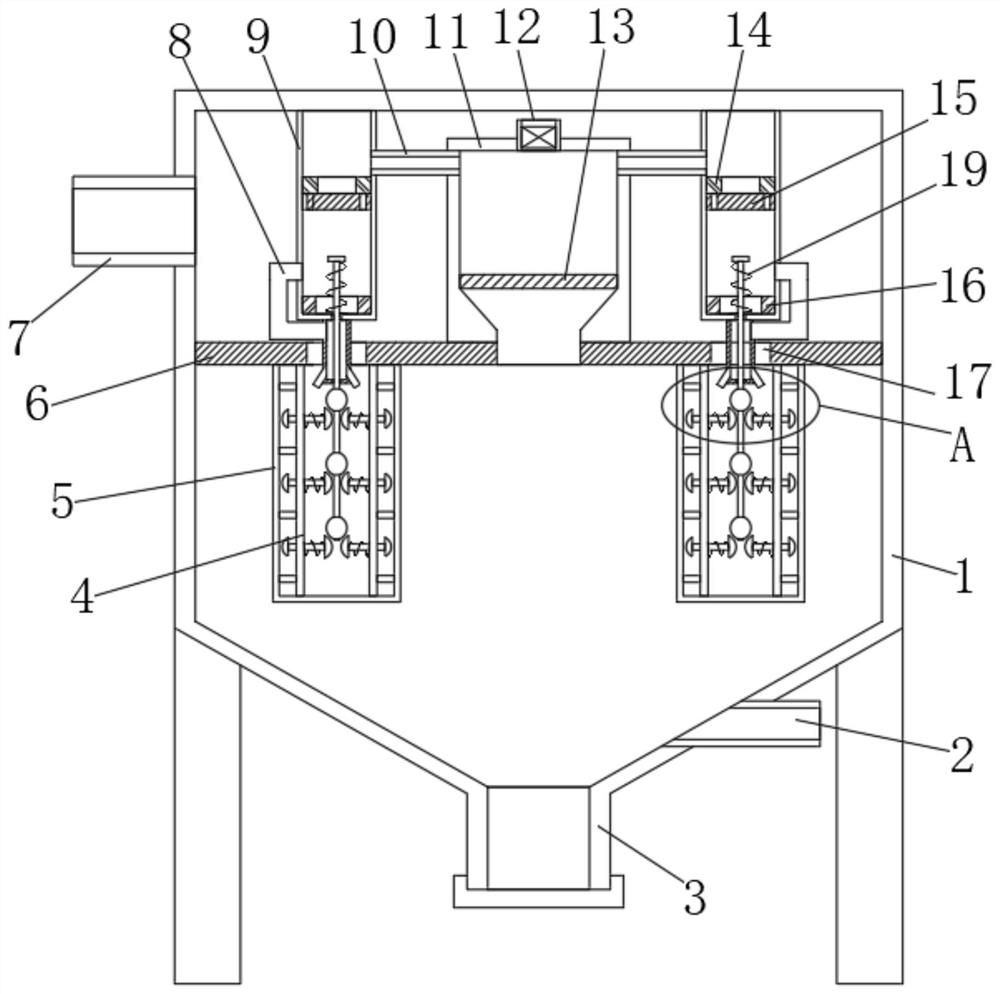
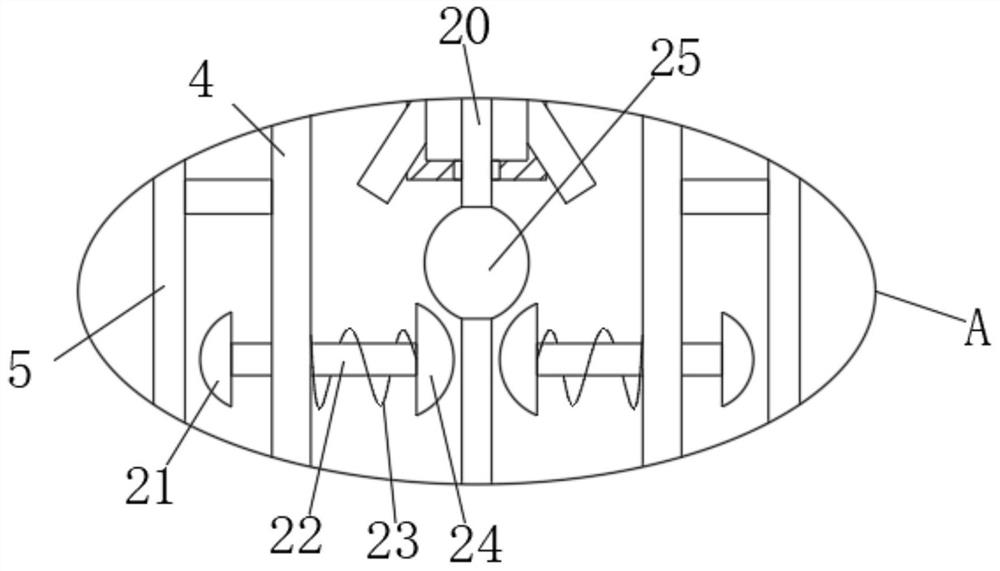
[0027] refer to Figure 2-3 The difference between embodiment two and embodiment one is that a toggle mechanism is provided in the fixed frame 4 of this embodiment, and the toggle mechanism includes a movable rod 20 vertically arranged on the inner side of the fixed frame 4, and the upper end of the movable rod 20 is sequentially Through the air injection pipe 18, the first fixed cylinder 9 and extend to the inner side of the first fixed cylinder 9, the upper end of the movable rod 20 is fixedly connected with the limit block, and the movable rod 20 is located on the side wall of the first fixed cylinder 9 and is sleeved with a first Spring 19, the two ends of the first spring 19 are respectively fixedly connected on the limit block, the inner bottom wall of the first fixed cylinder 9, and the movable rod 20 is positioned on the side wall in the fixed frame 4 and is fixedly sleeved with a plurality of fixed parts at equal intervals. The ball 25 is equipped with a plurality of ...


PUM


Abstract

The invention discloses an improved bag filter, which comprises a casing and an air inlet end and an air outlet connected to the casing. The lower end of the casing is provided with an ash bucket, and the inside of the casing is fixedly connected with a The partition board is provided, and the partition board divides the inside of the shell into an air outlet chamber and an air filter chamber arranged up and down. There is a pressure storage mechanism, the upper surface of the partition plate is equidistantly spaced along its circumference and provided with a plurality of air vents, and the lower end surface of the partition plate is fixedly connected with a plurality of fixing brackets corresponding to the positions of the air vents at equal intervals along its circumferential direction . The present invention can loosen and blow down the dust on the surface of the filter bag through the set pressure storage mechanism, constant pressure air injection mechanism and toggle mechanism when the filter bag surface area is more dust and the air filtration resistance increases and the air filtration efficiency decreases, and the dust removal is completed. The self-cleaning operation of the dust accumulated on the surface of the filter bag is energy-saving and environmentally friendly.

Description

technical field [0001] The invention relates to the technical field of bag filter, in particular to an improved bag filter. Background technique [0002] The bag filter is suitable for collecting fine, dry, non-fibrous dust. The filter bag is made of textile filter cloth or non-woven felt. The filter function of the fiber fabric is used to filter the dusty gas. After the bag filter, big particles will settle down due to the effect of gravity and fall into the hopper. When the gas containing fine dust passing through the filter material, the dust will be blocked and the gas will be purified. [0003] With the increase of the surface area of ​​the filter bag, the air filtration resistance of the filter bag increases and the efficiency of the filter air decreases. The existing one generally uses an external high-pressure air injection pipe to blow off the ash accumulation inside the filter bag, which is not convenient enough, and it is not energy-saving and environmentally frie...

Claims


Application Information

Patent Timeline
Patent Type & Authority Patents(China)
IPC IPC(8): B01D46/02B01D46/04
CPCB01D46/023B01D46/04
Inventor 刘术毅
Owner 山东巨佳生物科技有限公司
Why Eureka
Try Eureka