Soil remediation system for in-situ microorganisms

A soil remediation and microbial technology, which is applied in the field of soil remediation equipment, can solve the problems of volatile nutrients, microbial death, and high equipment cost, and achieve the effects of shortening the repair cycle, increasing the degradation rate, and reducing equipment cost

Active Publication Date: 2019-10-22
克拉玛依市新奥达石油技术服务有限公司
View PDF7 Cites 11 Cited by
  • Summary
  • Abstract
  • Description
  • Claims
  • Application Information

AI Technical Summary

Problems solved by technology

[0003] However, in situ microbial remediation at noon in hot summer with strong sunlight, the activity of microorganisms will be greatly reduced under the sun exposure, thereby slowing down the degradation rate and prolonging the remediation cycle of contaminated soil. At the same time, under high temperature, nutrients such as N and P are easily Volatile, and microorganisms will die under continuous exposure
[0004] In the existing technology, in order to pursue a shorter repair cycle, it is necessary to artificially cover the sunshade net at noon to block the strong sunlight, and then lift the sunshade net when the temperature is suitable in the afternoon to allow photosynthetic bacteria and other microorganisms that need sunlight to metabolize Degrading pollutants not only consumes manpower, but also the weather is hot at noon, and people exposed to the sun are prone to heatstroke; if intelligent equipment is used for automatic bedding, the cost of equipment will be high, and the installation of automated equipment in pursuit of a shorter repair cycle will not be worth the candle.

Method used


Image

  • Soil remediation system for in-situ microorganisms
  • Soil remediation system for in-situ microorganisms
  • Soil remediation system for in-situ microorganisms

Examples


Embodiment Construction

[0017] The following will clearly and completely describe the technical solutions in the embodiments of the present invention with reference to the accompanying drawings in the embodiments of the present invention. Obviously, the described embodiments are only some, not all, embodiments of the present invention.

[0018] In describing the present invention, it should be understood that the terms "upper", "lower", "front", "rear", "left", "right", "top", "bottom", "inner", " The orientation or positional relationship indicated by "outside", etc. is based on the orientation or positional relationship shown in the drawings, and is only for the convenience of describing the present invention and simplifying the description, rather than indicating or implying that the referred device or element must have a specific orientation, so as to Specific orientation configurations and operations, therefore, are not to be construed as limitations on the invention.

[0019] refer to Figure ...


PUM


Abstract

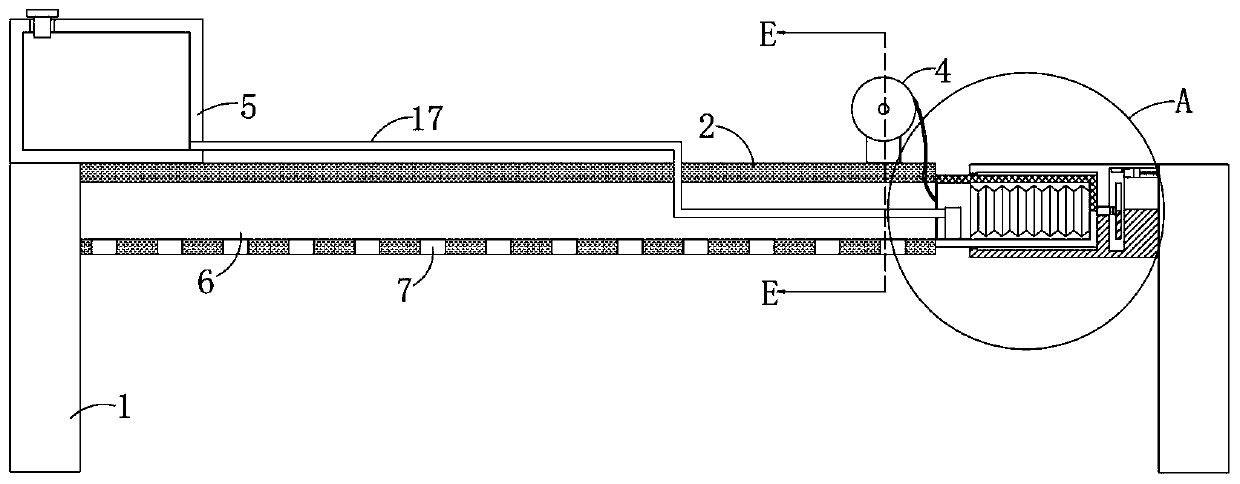
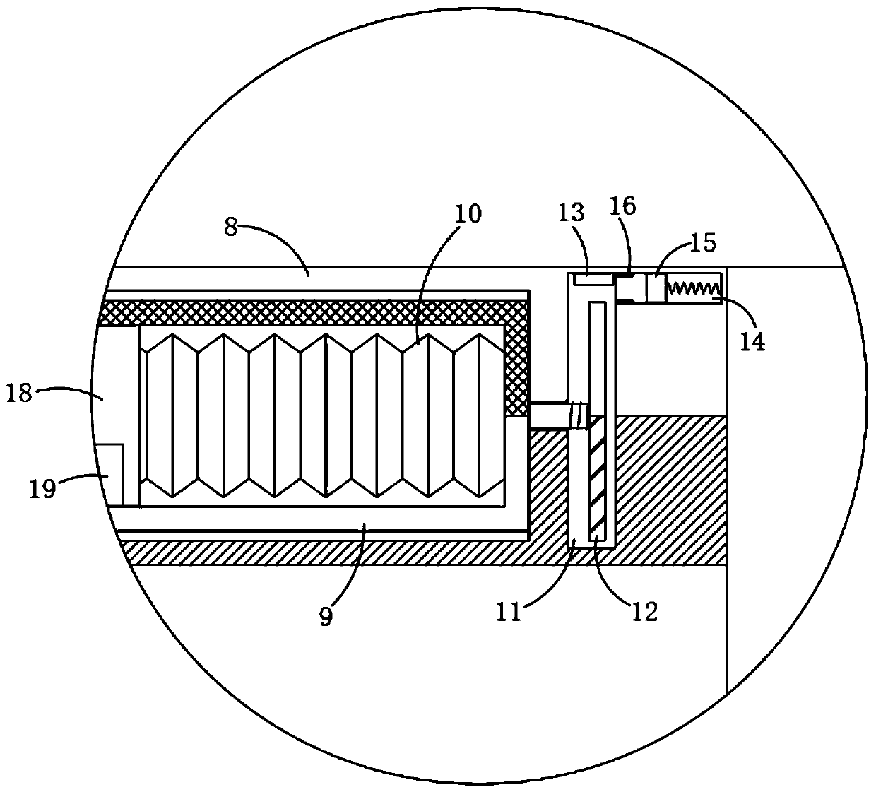
The invention discloses a soil remediation system for in-situ microorganisms. The soil remediation system comprises two parallel bar blocks, wherein bar grooves are formed in the side walls of the twobar blocks respectively; the opposite side walls of the bar blocks are rotationally connected with a roller together; a sunshade net is wound on the roller; one end of each bar block is rotationallyconnected with a first transparent barrel respectively; the inner wall of each first transparent barrel is fixedly connected with a telescopic air bag; and each telescopic air bag is filled with an evaporating solution with low boiling point. The first transparent barrels are driven by magnetic force to rotate, the transparent parts of the first transparent barrels and second transparent barrels are overlapped, sunlight can be irradiated into the first transparent barrels, the evaporating solution with low boiling point inside the telescopic air bags is gasified by heat absorption, sliding plugs are pushed to move forwards to the interiors of the bar grooves, and then the sunshade net can be driven to move for spreading, so that the sunshade net can be spread automatically at high noon without manual operation, and the system is simple in structure and low in equipment cost.

Description

technical field [0001] The invention relates to the technical field of soil remediation equipment, in particular to an in-situ microbial soil remediation system. Background technique [0002] In-situ microbial remediation does not need to remove the contaminated soil from the site, but directly puts nutrients such as N and P and oxygen supply into the contaminated soil to promote the metabolic activity of indigenous microorganisms or special functional microorganisms in the soil and degrade pollutants. [0003] However, in situ microbial remediation at noon in hot summer with strong sunlight, the activity of microorganisms will be greatly reduced under the sun exposure, thereby slowing down the degradation rate and prolonging the remediation cycle of contaminated soil. At the same time, under high temperature, nutrients such as N and P are easily Volatile, and microorganisms will die under continuous exposure. [0004] In the existing technology, in order to pursue a shorte...

Claims


Application Information

Patent Timeline
Patent Type & Authority Applications(China)
IPC IPC(8): B09C1/10
CPCB09C1/10B09C2101/00
Inventor 何条红
Owner 克拉玛依市新奥达石油技术服务有限公司
Why Eureka
Try Eureka