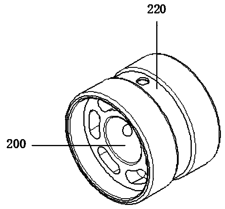
Ceramic wheel for printing

A technology of printing wheels and ceramics, which is applied in printing, printing machines, printing processes, etc., can solve problems such as time-consuming, insufficient adsorption force, and poor practicability, so as to increase transmission friction, ensure printing quality, and increase The effect of practicality

Pending Publication Date: 2019-10-22
广东拓品智能机械科技有限公司
View PDF0 Cites 2 Cited by
  • Summary
  • Abstract
  • Description
  • Claims
  • Application Information

AI Technical Summary

Problems solved by technology

[0002] With the development of society, the traditional printing production methods are no longer suitable for people's fast pace of life. General printing equipment often requires a lot of labor, and a lot of manpower is needed to operate the machine and take care of the equipment, which not only costs a lot of money for production time, and the cost is also greatly increased. When the printing machine is working, the negative pressure provided by the negative pressure bellows can accurately transfer the supported cardboard to the next working position. However, most of the existing printing wheels are made of Made of metal, the surface will become smooth after working for a period of time, resulting in insufficient adsorption force. At the same time, most of the existing printing wheels do not have suction grooves, and the adsorption force and transmission friction force are insufficient, which easily causes the cardboard to shift during transmission. Phenomenon, will affect the printing quality, practicality is not strong

Method used


Image

  • Ceramic wheel for printing
  • Ceramic wheel for printing
  • Ceramic wheel for printing

Examples


Embodiment Construction

[0017] In order to make the above objects, features and advantages of the present invention more comprehensible, specific implementations of the present invention will be described in detail below in conjunction with the accompanying drawings.

[0018] In the following description, a lot of specific details are set forth in order to fully understand the present invention, but the present invention can also be implemented in other ways different from those described here, and those skilled in the art can do it without departing from the meaning of the present invention. Similarly generalized, the present invention is therefore not limited by the specific embodiments disclosed below.

[0019] Secondly, the present invention is described in detail in conjunction with schematic diagrams. When describing the implementation of the present invention in detail, for the convenience of explanation, the cross-sectional view showing the device structure will not be partially enlarged accor...


PUM


Abstract

The invention belongs to the technical field of printing equipment, and particularly relates to a ceramic wheel for printing. The ceramic wheel for printing comprises a fan and a printing ceramic wheel body, wherein an air outlet of the fan is connected with an air pipe; the end part of the air pipe is connected with a distribution air pipe; the top of the distribution air pipe is provided with anegative pressure air box; the printing ceramic wheel body is arranged on the negative pressure air box; the printing ceramic wheel body comprises a connecting shaft rod and an air suction groove; andthe connecting shaft rod penetrates through the negative pressure air box. According to the ceramic wheel for printing, the friction force between the printing ceramic wheel body and a production paperboard is enhanced through the grinding structure of the surface of the printing ceramic wheel body; meanwhile, the air pressure is generated through the work of the fan, and the air pressure is increased to the maximum through the matching of the air pipe, a connecting pipe and a ventilation pipe; and the air suction groove arranged on the printing ceramic wheel is matched with the negative pressure generated by the negative pressure air box, so that the adsorption force and the transmission friction force between the printing ceramic wheel body and the paperboard are increased, the frequency that the paperboard is displaced in the transmission process is reduced, the printing quality is guaranteed, and the practicability of the ceramic wheel for printing is increased.

Description

technical field [0001] The invention relates to the technical field of printing, in particular to a ceramic wheel for printing. Background technique [0002] With the development of society, the traditional printing production methods are no longer suitable for people's fast pace of life. General printing equipment often requires a lot of labor, and a lot of manpower is needed to operate the machine and take care of the equipment, which not only costs a lot for production time, and the cost is greatly increased. When the printing machine is working, the negative pressure provided by the negative pressure bellows can accurately transfer the supported cardboard to the next working position. However, most of the existing printing wheels are made of Made of metal, the surface will become smooth after working for a period of time, resulting in insufficient adsorption force. At the same time, most of the existing printing wheels do not have suction grooves, and the adsorption forc...

Claims


Application Information

Patent Timeline
Patent Type & Authority Applications(China)
IPC IPC(8): B41F13/10B41N1/22
CPCB41F13/10B41N1/22
Inventor 易槐友虞剑明
Owner 广东拓品智能机械科技有限公司
Why Eureka
Try Eureka