Pen

A pen holder and refill technology, applied to pen holders, printing, writing utensils, etc., can solve the problems of affecting teaching time, difficult to pull out the pen cap, discarding the pen cap, etc., and achieve the effects of wide application, manpower saving and integrity assurance

Pending Publication Date: 2019-10-22
XIAN NAXIENIAN TECH NETWORK
View PDF0 Cites 0 Cited by
  • Summary
  • Abstract
  • Description
  • Claims
  • Application Information

AI Technical Summary

Problems solved by technology

[0004] 1. When the pen cap is blocked or opened, a certain amount of strength is required. When the buckle is tight or the user is weak, the cap is not easy to pull out, causing inconvenience in use and even affecting the teaching time;
[0005] 2. Most of the pen cap and the pen holder are connected by a buckle. After many times of use, the buckle becomes loose, and the pen cap cannot be well matched with the pen holder, resulting in the loss of the pen cap;
[0006] 3. In the whiteboard pen, the refill is connected to the ink. When opening it, if you use too much force, it will easily cause the ink to spill from the refill, stain your clothes or hands, and cause pollution to the peripheral environment;
[0007] In the prior art, if the pen cap is pulled out many times, the ink is unstable, and it is easy to flow out from the pen core and flow into the pen cap, resulting in waste of ink. throw away

Method used


Image

  • Pen
  • Pen
  • Pen

Examples


Embodiment 1

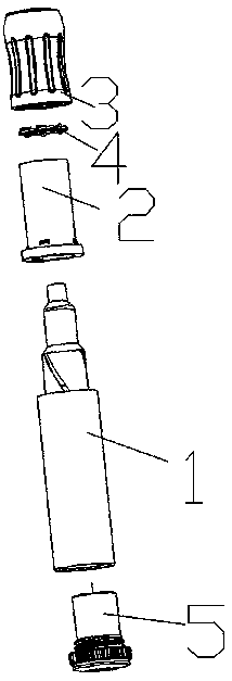
[0051] Refer to attached figure 1 As shown, the present embodiment mainly discusses how to realize the opening of the movable plate 4 in the whole pen structure, specifically:

[0052] A pen, comprising a penholder 1 and a refill 101 arranged on the penholder 1, a sleeve 2 and a rotating cylinder 3 are sequentially sleeved on the outside of the penholder 1, and the rotating cylinder 3 is rotatably connected to the sleeve 2;

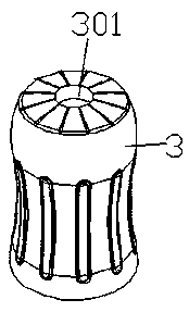
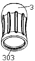
[0053] Refer to attached figure 2 and attached Figure 8 As shown, the sleeve 2 and the drum 3 are respectively provided with a first perforation 201 and a second perforation 301. The positions of the first perforation 201 and the second perforation 301 correspond to each other. When the drum 3 rotates, it drives the penholder 1 to move, so that The refill 101 passes through the first hole 201 and the second hole 301, and is exposed on the top of the drum 3 or hidden in the sleeve 2;

[0054] A movable plate 4 is provided between the sleeve 2 and the ...

Embodiment 2

[0060] On the basis of Embodiment 1, this embodiment describes the specific structure of the movable plate 4 .

[0061] Specifically, refer to the attached Figure 2-4 As shown, there are several first sliding slots 302 , and the several first sliding slots 302 are arranged along the outer periphery of the second through hole 301 , specifically on the inner wall, and each first sliding slot 302 is correspondingly provided with a movable plate 4 . There are a plurality of movable plates 4, which are arranged corresponding to the first chute 302, so that it is convenient to be arranged as a structure such as an arc with sharp corners, and a plurality of sharp corners are combined to form a circular structure, so as to realize the shielding of the first perforation 201, and then the pen The core 101 cannot be exposed through the first through hole 201 . Specifically, when rotating, a plurality of movable plates 4 move toward the top of the first perforation 201 at the same time,...

Embodiment 3

[0065] In this embodiment, the description mainly focuses on the limitation in the movement of the movable plate 4 .

[0066] Refer to attached Figure 5-7 As shown, further, the other side of the movable plate 4 is provided with a limit block 402, through the attachment Figure 8-10 As shown, the outer wall of the sleeve 2 is provided with a limiting slot 202 for the movement of the limiting block 402, specifically, the limiting block 402 is a cylindrical structure. By setting the limit block 402 and the limit groove 202, when the slider 401 slips or the first chute 302 fails to cause the slider 401 to derail, it can play a limiting role, and at the same time, it can realize the movement of the entire movable plate 4. Activity. Refer to attached Figure 5-7 As shown, for the movable plate 4, the limit block 402 is set on the other side, so that the two sides of the movable plate are respectively provided with convex structures to increase its strength. If they are arranged...


PUM


Abstract

The invention discloses a pen. The pen comprises a pen holder and a pen refill arranged on the pen holder, wherein the pen holder is sleeved with a sleeve and a rotary cylinder sequentially; the rotary cylinder is rotatably connected with the sleeve; a first through hole and a second through hole are respectively formed in the sleeve and the rotary cylinder; when the rotary cylinder rotates, the pen holder is driven to move, so that the pen refill is made to penetrate through the first through hole and the second through hole to be exposed out of the top of the rotary cylinder or hidden in thesleeve; a movable plate is arranged between the sleeve and the rotary cylinder; and when the rotary cylinder rotates, the movable plate is driven to move to be close to or far away from the upper part of the first through hole, and therefore the pen refill is blocked or communicate with the outside; and the length of the pen holder is 12-18 cm. Due to the rotation of the rotary cylinder, multipleeffects of exposing, blocking and the like of the pen refill are achieved, force is saved, the problem of ink overflow is avoided, and the effect of rotating the pen refill is achieved.

Description

technical field [0001] The invention relates to the technical field of office supplies, in particular to a pen structure through which the core is ejected and the core is blocked by rotation. Background technique [0002] With the development of science and technology, the traditional teaching mode has also changed, among which the change of traditional teaching tools is the most prominent. Specifically, traditional teaching tools are mostly chalk, but now they are changed to whiteboard pens. Whiteboard pens, also known as marker pens, are writing utensils that use ink as a medium, effectively replacing traditional chalks. It can completely make up for the adverse effects of dust and other adverse effects caused by traditional chalk after use. [0003] In the prior art, the whiteboard markers are blocked by fastening the pen cap, which has the following defects: [0004] 1. When the pen cap is blocked or opened, a certain amount of strength is required. When the buckle is ...

Claims


Application Information

Patent Timeline
Patent Type & Authority Applications(China)
IPC IPC(8): B43K24/06B43K3/00
CPCB43K3/00B43K24/06
Inventor 吴睿富
Owner XIAN NAXIENIAN TECH NETWORK
Why Eureka
Try Eureka