
System for reducing air friction resistance on surfaces of train by blowing air to interfere in air flow

A technology that interferes with airflow and air friction. It is used in railway car body, fluid flow, climate sustainability and other directions. It can solve the problem that straight holes cannot be closed, and achieve the effect of reducing resistance.

Active Publication Date: 2019-10-22
TONGJI UNIV
View PDF7 Cites 3 Cited by
  • Summary
  • Abstract
  • Description
  • Claims
  • Application Information

AI Technical Summary

Problems solved by technology

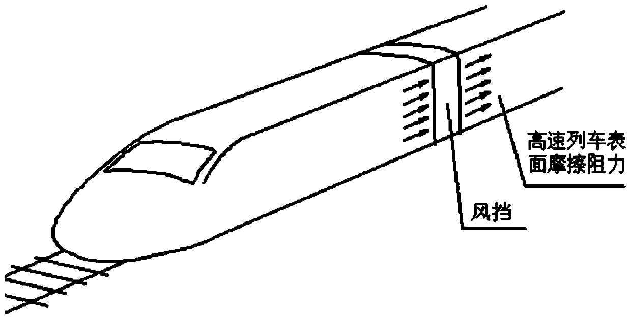
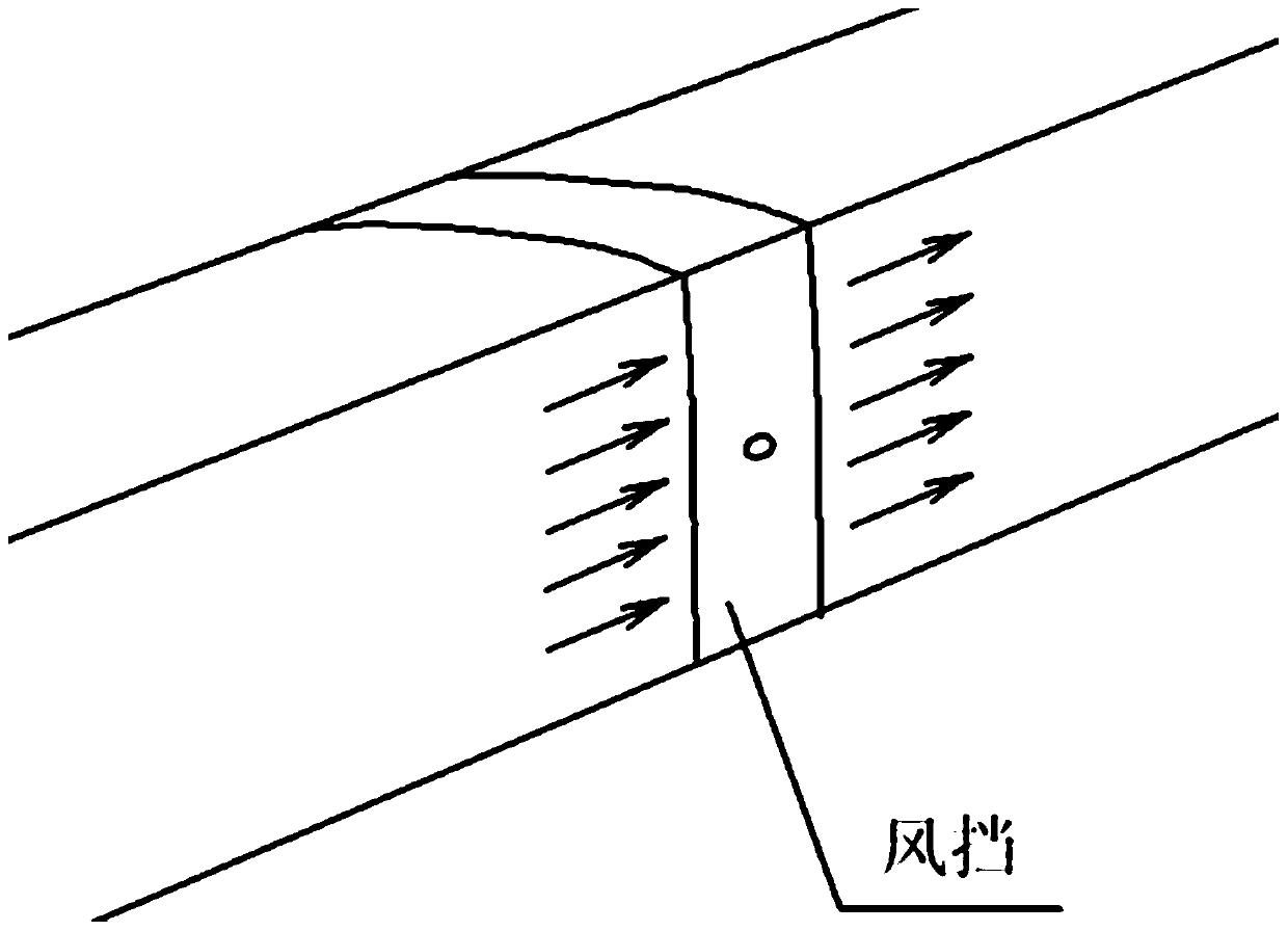
If also punch straight holes, punch a straight hole or punch a row of straight holes, set the position of punching just at the windshield position of the train, this straight hole will also have such shortcoming, when not needing to blow air, this straight hole becomes a source of resistance
There is no way to close the straight hole, and there is no facility with the sealing function

Method used


Image

  • System for reducing air friction resistance on surfaces of train by blowing air to interfere in air flow
  • System for reducing air friction resistance on surfaces of train by blowing air to interfere in air flow
  • System for reducing air friction resistance on surfaces of train by blowing air to interfere in air flow

Examples


Embodiment Construction

[0038] The invention provides a system for reducing the air friction resistance of the train surface by interfering with the air flow in a blowing manner.

[0039] The blowing technology applied to high-speed trains should be able to blow when moving forward, and the direction is to blow to the side and rear to reduce frictional resistance. When the train is traveling in the reverse direction, the blowing holes will change to face the direction of travel. At this time, close the blow hole. In this way, on the outermost surface of the train, a convex-shaped surface is adopted. The blow hole can be opened behind the train in the forward direction, and the blow hole can be closed in front of the train. That is to say, in one direction, blowing is achieved, while blowing, the blowing holes on the surface of the car body can also be sealed; in the other direction, the blowing holes on the car body can be closed.

[0040] Specifically, the system of the present invention to interfere wi...


PUM


Abstract

The invention provides a system for reducing air friction resistance on surfaces of a train by blowing air to interfere in air flow. The system comprises a plurality of convex-peak-shaped air blowingunits longitudinally arranged on wall surfaces of a gangway bellows of the train. The air blowing directions of the air blowing units are opposite to the direction in which the train runs, and the airblowing directions of all the air blowing units are the same; each of the air blowing units comprises two air blowing openings which are both positioned on inclined surfaces of the corresponding convex peak shape and which form a certain included angle with the plane of the corresponding outer surface of the train; one of the two air blowing openings is in the reverse direction to the direction in which the train runs so as to achieve air blowing and sealing, and the other air blowing opening is in the same direction as the direction in which the train runs so as to achieve sealing; inside the train, the air blowing units comprise first systems, second systems and supporting and rotating mechanisms; the first systems and the second systems are separately clamped, supported and rotated through the supporting and rotating mechanisms; the first systems comprise air blowing devices and compression devices so as to separately achieve air blowing and compression sealing; and the second systems comprise compression devices so as to achieve compression sealing.

Description

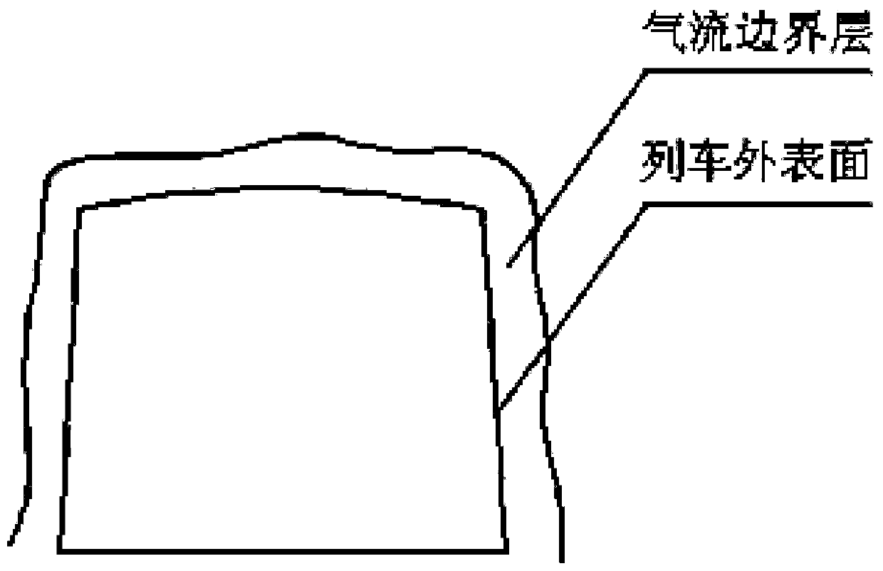
Technical field [0001] The invention belongs to the technical field of air friction resistance of high-speed trains, and in particular relates to a system that interferes with air flow in a blowing manner to reduce the air friction resistance of the train surface. Background technique [0002] High-speed trains provide great convenience for people's travel. According to the technological development trend of high-speed trains, higher speed trains are now being studied. Such as figure 1 with figure 2 As shown, when the train is running at high speed, the interaction between the air and the surface of the car body produces a boundary layer of the air close to the surface of the car body, which is also the source of high-speed frictional resistance on the surface. That is, as the speed increases, the interaction between the surface of the car body and the air gradually strengthens, and the air resistance continues to increase. In order to reduce the friction between the surface of...

Claims


Application Information

Patent Timeline
IPC IPC(8): B61D17/02F15D1/06
CPCB61D17/02F15D1/06Y02T30/00
Inventor 余志壮
Owner TONGJI UNIV
Learn More