Full-automatic deviation correcting mechanism of printing machine

A printing machine, fully automatic technology, applied in the field of deviation correction mechanism, can solve the problems of high work intensity, low printing machine work efficiency, heavy workload, etc., and achieve the effect of stable structure and wide application range

Inactive Publication Date: 2019-10-22
武汉天利包装有限公司
View PDF8 Cites 2 Cited by
  • Summary
  • Abstract
  • Description
  • Claims
  • Application Information

AI Technical Summary

Problems solved by technology

However, the work intensity of manual adjustment and deviation correction is relatively high, and it is necessary to keep an eye on the conveying track of the pla

Method used


Image

  • Full-automatic deviation correcting mechanism of printing machine
  • Full-automatic deviation correcting mechanism of printing machine
  • Full-automatic deviation correcting mechanism of printing machine

Examples


Embodiment 1

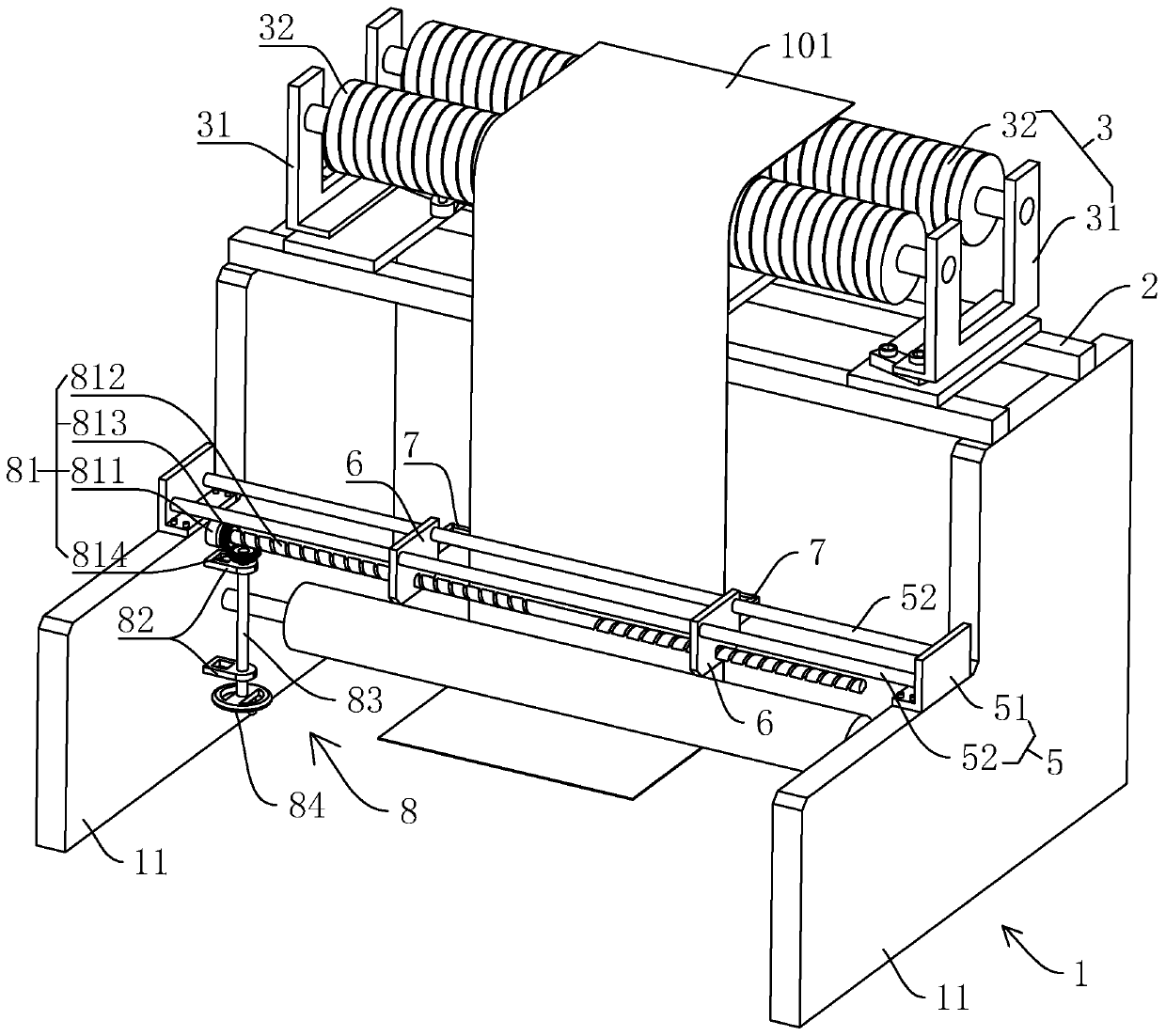
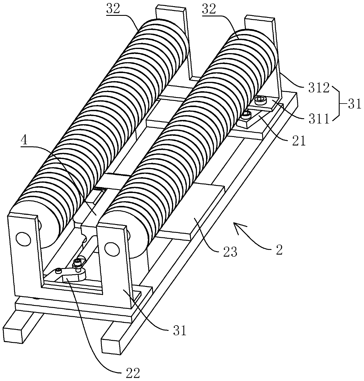
[0041] refer to figure 1 and figure 2 , is a deviation correction mechanism of a fully automatic printing machine disclosed in the present invention, comprising: a frame 1, a horizontal support frame 2, a deviation correction roller group 3, a deviation correction driver 4, a horizontal guide 5, a sliding plate 6, and a U-shaped photoelectric sensor 7. Manually synchronizing the driving part 8 and the control module (in this embodiment, it is specifically referred to as controlling the PLC and the computer, and is not specifically shown in the drawings).

[0042] The frame 1 is composed of two side plates 11 arranged in parallel and at intervals. In other implementations, support rods can be added between the two side plates 11 to enhance the structural strength of the entire frame 1. The horizontal support frame 2 is fixed on two Between the side plates 11, the deviation-correcting roller group 3 is movably connected to the horizontal support frame 2, and the deviation-corr...

Embodiment 2

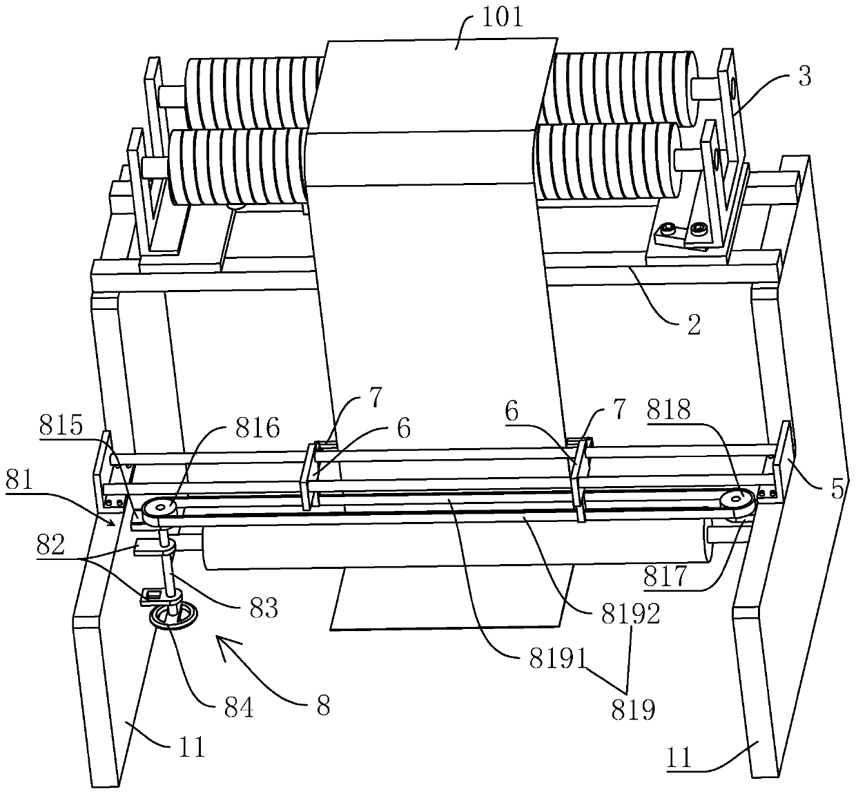
[0057] refer to image 3, is a deviation correction mechanism of a fully automatic printing machine disclosed in the present invention. The difference from Embodiment 1 is that the transmission member 81 includes: a first bracket 815, a driving pulley 816, a second bracket 817, and a driven pulley 818 and synchronous belt 819; the first bracket 815 is fixed on the inner wall of the side plate 11, the driving pulley 816 is rotatably assembled on the first bracket 815, the vertical rotation rod 83 drives the driving pulley 816 to rotate, and the second bracket 817 is fixed on the other side On the inner wall of the side plate 11, the driven pulley 818 is rotatably mounted on the second bracket 817, the timing belt 819 is sleeved between the driving pulley 816 and the driven pulley 818, and the driving pulley 816, the driven pulley 818 The rotation axes are arranged vertically; one sliding plate 6 is fixed to the first part 8191 of the synchronous belt 819, and the other sliding ...


PUM


Abstract

The invention relates to a full-automatic deviation correcting mechanism of a printing machine, and relates to the technical field of printing equipment. The deviation correcting mechanism comprises amachine frame, a horizontal supporting frame, a deviation correcting roller set, a deviation correcting driving part, a horizontal guide part, sliding plates, U-shaped photoelectric sensors, a manualsynchronous driving part and a control module; the machine frame is at least composed of two side plates which are arranged at intervals in parallel, the deviation correcting roller set is movably connected to the horizontal supporting frame, and the deviation correcting driving part drives the deviation correcting roller set to swing; the two sliding plates are assembled on the horizontal guidepart in a sliding mode, the two U-shaped photoelectric sensors are arranged on the two sliding plates respectively, and the manual synchronous driving part is used for driving the two sliding plates to synchronously move close to or away form each other; and when the U-shaped photoelectric sensors detect deviation of a product to be printed, the control module controls the deviation correcting driving part to start working. The deviation correcting mechanism has the advantages that the structure is stable, the purpose of correcting deviation can be achieved automatically, the deviation correcting mechanism is suitable for printing of products with different width sizes, and adjusting the position of the U-shaped photoelectric sensors is convenient.

Description

technical field [0001] The invention relates to the technical field of printing equipment, in particular to a deviation correcting mechanism of a fully automatic printing machine. Background technique [0002] With the continuous development of society, the use of plastic films is increasing (such as plastic packaging bags), and the requirements for the quality and appearance of plastic films are also getting higher and higher. In order to make the appearance of the plastic film more beautiful and meet the requirements of different fields, text and patterns are usually printed on the surface of the plastic film. [0003] When the printing machine in the prior art is working, the plastic film is very likely to be shifted during the transmission process. At this time, the staff needs to manually adjust the plastic film to correct the plastic film and ensure the stability of the plastic film transmission. There will be no offset to ensure the printing quality of text and patte...

Claims


Application Information

Patent Timeline
IPC IPC(8): B65H5/36B65H9/20
CPCB65H5/36B65H9/20B65H2701/1131
Inventor 孟汉池吴波
Owner 武汉天利包装有限公司
Why Eureka
Try Eureka