
Municipal engineering road crack pouring device facilitating residual material clearing

A residual material and municipal technology, applied in the field of road joint filling devices for municipal engineering, can solve the problems of reducing joint filling efficiency, secondary damage, inconvenient cleaning of residual materials, etc., to achieve smooth road surface for joint filling, avoid corrosion, and improve work efficiency Effect

Inactive Publication Date: 2019-10-22
江苏纵湖涂装设备产业研究院有限公司
View PDF0 Cites 19 Cited by
  • Summary
  • Abstract
  • Description
  • Claims
  • Application Information

AI Technical Summary

Problems solved by technology

[0004] The purpose of the present invention is to provide a kind of road joint filling device for municipal engineering that is convenient for cleaning residual materials, so as to solve the problem that the traditional road joint filling device proposed in the above-mentioned background technology uses asphalt for a long time to easily stick to the inner wall of the device barrel, corrode the device, It is inconvenient to clean up the residual material. Because there are a lot of dust and impurities in the road gap, it is easy to cause the filling to be weak when filling. In cold weather, due to the low temperature, asphalt and other joint filling oil cannot be combined with the road surface in time. , it is easy to cause secondary damage under the rolling in the car and reduce the efficiency of joint filling

Method used


Image

  • Municipal engineering road crack pouring device facilitating residual material clearing
  • Municipal engineering road crack pouring device facilitating residual material clearing
  • Municipal engineering road crack pouring device facilitating residual material clearing

Examples


Embodiment Construction

[0027] The following will clearly and completely describe the technical solutions in the embodiments of the present invention with reference to the accompanying drawings in the embodiments of the present invention. Obviously, the described embodiments are only some, not all, embodiments of the present invention. Based on the embodiments of the present invention, all other embodiments obtained by persons of ordinary skill in the art without making creative efforts belong to the protection scope of the present invention.

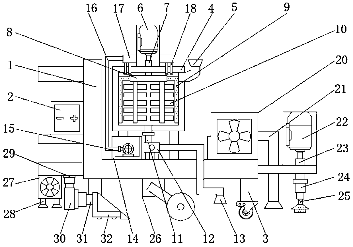
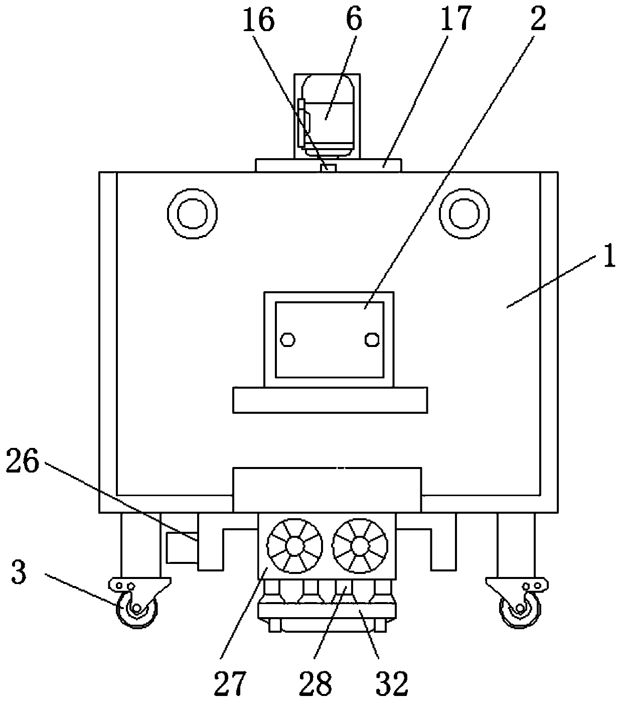
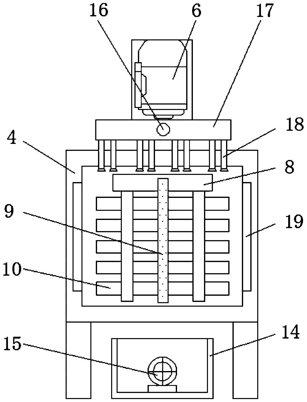
[0028] see Figure 1-6 , the present invention provides a technical solution: a road joint filling device for municipal engineering that is convenient for cleaning residual materials, such as figure 1 , figure 2 and image 3 As shown, the left side of the device body 1 is provided with a power supply box 2, and the lower end of the device body 1 is provided with a roller 3, the upper surface of the device body 1 is provided with a storage tank 4, and the ri...


PUM


Abstract

The invention discloses a municipal engineering road crack pouring device facilitating residual material clearing. The municipal engineering road crack pouring device facilitating residual material clearing comprises a device body, a collecting box and a leveling device, the outer side of a scraping plate is in contact with the inner side wall of a storage tank, an annular pipe is arranged on theouter side of a first motor, moreover, a water spraying pipe is arranged at the lower end of the annular pipe, the right side of the collecting box is provided with a dust suction pipe, a second rotating rod penetrates through the upper surface of the device body to be connected with a first hydraulic telescopic rod, moreover, a brush is arranged at the lower end of the first hydraulic telescopicrod, the leveling device is arranged at the lower end of the device body, an air heater is arranged at the lower end of the device body, a second hydraulic telescopic rod is arranged at the right endof a connecting block, and a scraping hopper is arranged at the right end of the second hydraulic telescopic rod. According to the municipal engineering road crack pouring device facilitating residualmaterial clearing, after crack pouring is finished, a water pump can be used for spraying water in a water tank on the inner side wall of the storage tank through the water spraying pipe, and a motoris used for driving the scraping plate to clear residual materials left on the inner side wall of the storage tank.

Description

technical field [0001] The invention relates to the technical field of road joint filling devices, in particular to a road joint filling device for municipal engineering that is convenient for cleaning residual materials. Background technique [0002] In recent years, with the economic and social development of our country and the expansion of urban scale, the traffic has been increasing continuously, and the urban roads built in the early stage have been damaged to varying degrees, which affects the performance of urban roads, and road cracks need to be repaired. Just need to use road joint filling device. [0003] The traditional road joint filling device uses asphalt for a long time to easily stick to the inner wall of the device barrel, corrode the device, and it is not convenient to clean up its residue. Because there are more dust and impurities in the road gap, it is easy to cause the filling to be weak. , In cold weather, due to the low temperature, asphalt and othe...

Claims


Application Information

Patent Timeline
Patent Type & Authority Applications(China)
IPC IPC(8): E01C23/09
CPCE01C23/096
Inventor 鲍雪
Owner 江苏纵湖涂装设备产业研究院有限公司
Learn More